24
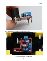
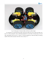
The eighth step is to connect the motor wires to the drive, note that the rotation direction of the two
motors require to be identical, so we should modify and debug the program first when wiring. Connecting the
motor to any motor driver board, as shown in Fig.3.1.13, then connecting the two wires on battery box to the
motor drive +12v (red) and GND (black), and leading a wire from +5V to "3" or "4" in the figure(IN1&IN2
is a motor set, IN3&IN4 is another set). Observing rotation directions of the motors, if the rotation directions
are not the same, you only need to change "1" and "2" in the figure. The physical map is shown in Fig.3.1.14.
Fig.3.1.13 Diagram of Connection Between Motors and Drive Board
Summary of Contents for Hummer-Bot
Page 1: ...Hummer Bot Instruction Manual Github https github com keywish keywish hummer bot...
Page 7: ...4...
Page 8: ...5...
Page 9: ...6...
Page 10: ...7...
Page 13: ...10 Fig 2 2 Several commonly usedArduino...
Page 15: ...12 After the completion as shown...
Page 16: ...13 The second step is to Welding wire on the motor...
Page 17: ...14 After the completion as shown...
Page 19: ...16 Fig 3 1 3 Diagram of Aluminum Alloy Bracket Installation...
Page 20: ...17 Fig 3 1 4 Diagram of Motor Installation Fig 3 1 5 Fixing Screw for Motor...
Page 24: ...21 Fig 3 1 10 Diagram of Wheel Installation Fig 3 1 10 Diagram of Wheel Screw Fixation...
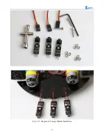
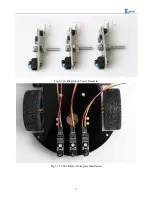
Page 29: ...26 Fig 3 1 15 Diagram of Tracing Module Installation...
Page 30: ...27 Fig 3 1 16 Diagram of Screw Brackets Fig 3 1 17 The Back of Complete Installation...
Page 32: ...29 First install the screws on the UNO After the completion as shown...
Page 43: ...40 Fig 3 1 33 Diagram of Wires Arrangement Fig3 1 34 the Effect of Whole Assembly...
Page 56: ...53 Fig 3 2 11 Diagram of Data with Obstacles Fig 3 2 12 Diagram of Data without Obstacles...
Page 69: ...66 Fig 3 2 22 Diagram of Steering Gear Fig 3 2 23 Composition of Steering Gear...
Page 93: ...90 Fig 3 2 42 Receiving Head Position Fig 2 3 43 Installation of Receiving Head...


