100
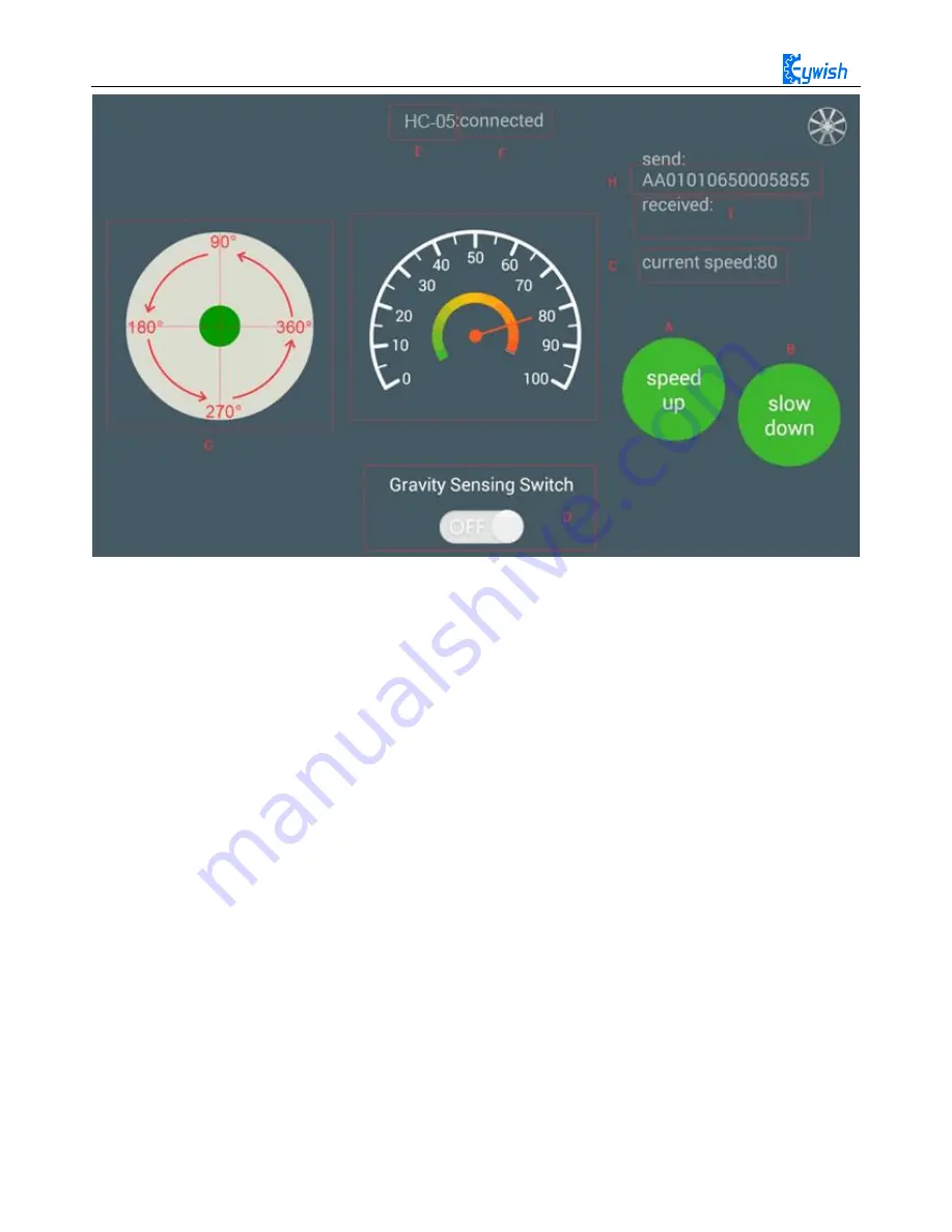
Fig.3.2.48 the Interface of Android APP
In the above Figure.3.2.48:
The "A, B" sections are the acceleration and deceleration buttons.
The "C" section includes the dashboard and the digital display area, and the two parts displaying
synchronously. They represents the current speed.
The "D" section is a gravity remote sensing switch which can be switched to the gravity remote sensing
mode.
The "E" section represents the Bluetooth name that is currently connected.
The "F" section indicates Bluetooth connection state. If the Bluetooth is not connected, the "disconnected" is
displayed here.
The "G" section is a manual rocker, and sliding it allows the car to rotate.
The "I" section is a data return area, such as the current state, speed of the car, etc. The "H" section is the
data packet, for example, the data is "AA 01 01 06 23 00 2B 55". At this time, the speed is 35 (23 is 16
hexadecimal data, which means 35 when converted to 10 hexadecimal).
If the transmitted data is "AA 01 01 05 00 5B 00 62 55", it means that the car is moving forward (05 is
the direction control instruction, and the 005B means 91 when converted to binary number. By the
Figure.3.2.48 we can know that 91 degree means the car is moving forward).
3.2.7.3 Experimental Procedures
Connect the Bluetooth module of the wire to "1" marked in Fig.3.2.50 Connection mode: HC-05 VCC port
on Bluetooth module is connected to Arduino 3.6V~6V DC power anode, GND port is connected to the
Summary of Contents for Hummer-Bot
Page 1: ...Hummer Bot Instruction Manual Github https github com keywish keywish hummer bot...
Page 7: ...4...
Page 8: ...5...
Page 9: ...6...
Page 10: ...7...
Page 13: ...10 Fig 2 2 Several commonly usedArduino...
Page 15: ...12 After the completion as shown...
Page 16: ...13 The second step is to Welding wire on the motor...
Page 17: ...14 After the completion as shown...
Page 19: ...16 Fig 3 1 3 Diagram of Aluminum Alloy Bracket Installation...
Page 20: ...17 Fig 3 1 4 Diagram of Motor Installation Fig 3 1 5 Fixing Screw for Motor...
Page 24: ...21 Fig 3 1 10 Diagram of Wheel Installation Fig 3 1 10 Diagram of Wheel Screw Fixation...
Page 29: ...26 Fig 3 1 15 Diagram of Tracing Module Installation...
Page 30: ...27 Fig 3 1 16 Diagram of Screw Brackets Fig 3 1 17 The Back of Complete Installation...
Page 32: ...29 First install the screws on the UNO After the completion as shown...
Page 43: ...40 Fig 3 1 33 Diagram of Wires Arrangement Fig3 1 34 the Effect of Whole Assembly...
Page 56: ...53 Fig 3 2 11 Diagram of Data with Obstacles Fig 3 2 12 Diagram of Data without Obstacles...
Page 69: ...66 Fig 3 2 22 Diagram of Steering Gear Fig 3 2 23 Composition of Steering Gear...
Page 93: ...90 Fig 3 2 42 Receiving Head Position Fig 2 3 43 Installation of Receiving Head...


