12
Keysight 87406Q Operating and Service Manual
2
Switch Configuration
General Operation
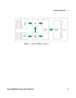
The 87406Q matrix switch consists of six ports which can be
individually connected via internal microwave switches to form an
RF path (see
Figure 2- 1
). When control inputs are sent to the
switch, the internal diode logic and position sensing circuitry
routes current to the appropriate solenoids to close or open the
microwave switches based on the input state. The position sensing
circuitry utilizes opto- electronic components to determine the
position of the individual internal microwave switches. Each
internal microwave switch has two solenoids: one to select or close
the RF port, and one to unselect or open the RF port. Each
solenoid requires 200 mA at 24 VDC nominal. The position sensing
circuits serve three purposes: to enable solenoids that need to be
switched, to interrupt the solenoid current once the individual
internal microwave switch is closed or opened, and to power the
position indicator circuits. The solenoid current is interrupted
once the switching solenoids are magnetically latched. The drive
current then returns to the standby level that is required by the
opto- electronic components. When a control input is applied, all
RF ports that have no enabling control input are automatically
opened by the internal logic circuitry.
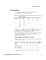
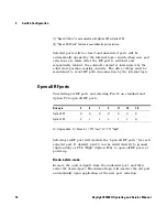
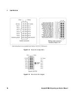
To configure a desired RF path, two ports must be engaged which
requires a control input for each port to be maintained. If the
input is removed from either port, that port will be automatically
opened by the internal logic circuitry. All of the "open" solenoids
are internally connected to pin 16 via diode logic circuitry (Option
161 and T24 only). If no input is present at any of the port select
pins (3, 5, 7, 9, 11, 13), all of the RF ports will be opened if pin
16 is selected. Input applied to port select pins (3, 5, 7, 9, 11, 13)
while pin 16 is selected will override the signal on pin 16 and
close the respective ports. On standard switches, pin 16 can be
permanently connected to ground to allow the switch to open all
RF ports at power up (assuming no input is present at any of the
port select pins). Not available with Options 100 or T24.
C A U T I O N
If pin 15 is not grounded, the logic circuit will not operate as expected, and
damage to the switch will occur.


