background image

 16

Keysight 41800A Active Probe

Operation
Overview

3-

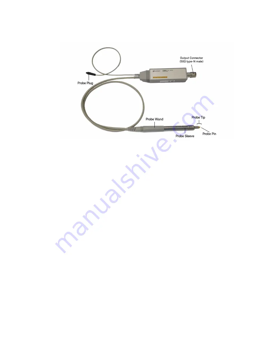
Figure 3-1 

41800A Probe Assembly

Probe Assembly 

(Protective Sleeve)

The 41800A probe assembly is equipped with a grounded protective sleeve to protect 

the probe tip from mechanical abuse and to reduce the chance of ESD damage. Extend 

the protective sleeve when not actually making measurements.
To retract the protective sleeve of the probe, perform the following procedure.

1.

Hold the probe wand, pointing the pin away from you, and grasp the protective sleeve 

in your other hand.

2. Turn the protective sleeve counter-clockwise a little.
3. Pull the sleeve slowly toward you.

4.

Turn the sleeve clockwise a little to lock it in position.

To extend the protective sleeve, perform the above steps in reverse order.

Summary of Contents for 41800A

Page 1: ...Operation Note Keysight 41800A Active Probe...

Page 2: ...e under the same terms by which the software is customarily provided to the public Accordingly Keysight provides the Software to U S gov ernment customers under its stan dard commercial license which...

Page 3: ...4 Original Packaging 14 Other Packaging 14 3 Operation Section Contents 15 Overview 15 Operating Precautions 19 Anti static Precautions 19 Maximum Allowable Level 20 Discharging The Probe 20 Preparati...

Page 4: ...ations at 23 C 5 C 42 Setup 42 Equipment 43 Procedure 43 Performance Test Record 45 5 Adjustment Introduction 47 Equipment Required 47 Preparation 47 LF Gain Flatness Adjustment 48 Description 48 Setu...

Page 5: ...lysis The following are the main features of the 41800A Wide frequency range 5 Hz to 500 MHz High input impedance 100 k 3 pF Used for both spectrum and network analyzers Protective sleeve to protect t...

Page 6: ...instruments with serial number prefixes listed under Serial Numbers on the title page Units manufactured after this operation note was printed may have a serial number prefix which is not listed on th...

Page 7: ...0A Refer to Figure 2 1 for details Table 1 2 Contents of the 41800A Description Quantity Probe Assembly 1 Keysight Probe BNC m Adapter 1 10 1 Divider 1 100 1 Divider 1 Slip on Spanner Ground Tip 1 Gro...

Page 8: ...stics are intended to provide information useful in applying the instrument by giving non warranted performance parameters These are denoted as typical nominal or approximate Bandwidth 5 Hz to 500 MHz...

Page 9: ...0 MHz input 3rd Order Intermodulation Distortion Typical 70 dBc at 26 dBm two signals input 400 MHz 400 5 MHz 1 dB Gain Compression 3 dBm input at 500 MHz Maximum Allowable Input DC AC 50 V probe alon...

Page 10: ...al Information Specifications 1 Furnished Accessories Probe BNC m Adapter 10 1 Divider 100 1 Divider Slip on Spanner Ground Tip Ground Clip flexible Probe Tip Nut Driver 3 32 inch 10229A Hook Tip Adap...

Page 11: ...al until the contents have been checked for completeness and the 41800A has been mechanically and electrically checked out Figure 2 1 shows the product overview of the 41800A The procedures for checki...

Page 12: ...part number 1 2 Probe BNC m Adapter P N 41800 60013 1 3 10 1 Divider P N 41800 60611 1 4 100 1 Divider P N 41800 60612 1 5 Slip on Spanner Ground Tip P N 5060 0549 1 6 Ground Clip flexible P N 41800...

Page 13: ...supply which meets the requirements listed in Figure 2 2 Figure 2 2 Probe Power Requirements Mating Connectors The output connector of the 41800A probe is a 50 N type male connector Trying to mate thi...

Page 14: ...g with commercially available materials 1 Wrap the unit in heavy paper or plastic If shipping to a Keysight sales office or service center attach a tag indicating the type of service required return a...

Page 15: ...tion Precautions Preparation For Use Typical Measurement Setups Probe Pin Replacement Overview This paragraph provides a description of the probe assembly and each of its furnished accessories includi...

Page 16: ...e Extend the protective sleeve when not actually making measurements To retract the protective sleeve of the probe perform the following procedure 1 Hold the probe wand pointing the pin away from you...

Page 17: ...g this divider the divider adjustment should be performed refer to Preparation for Use on page 20 Slip on Spanner Ground Tip This is used to ground the probe Put this ground tip on the probe to probe...

Page 18: ...kinds of probe pins 12 mil pin and 30 mil pin are available for the 41800A Three 12 mil pins and three 30 mil pins are furnished with the 41800A as spare probe pin set The 41800A is shipped from the f...

Page 19: ...onal floor mats provide an extra measure of protection especially in areas with floor carpet Do NOT use the 41800A on a carpeted work surface Hold the probe by the protective sleeve Always hold the pr...

Page 20: ...hould be repaired To verify that the 41800A meets its specifications perform the PERFORMANCE TEST described in SECTION 4 The 10 1 100 1 divider adjustments should be performed to minimize the frequenc...

Page 21: ...using a network analyzer To check the probe gain absolute power amplitude measurement mode should be selected Figure 3 4 Operating Check Setup Using a Network Analyzer CONFIG SPECTRUM PORT SELECT SOUR...

Page 22: ...as shown in Figure 3 4 2 Set up the network analyzer as follows 3 Confirm that the signal level is 4 dBm 5 dB Operating Check Using a Spectrum Analyzer Figure 3 5 shows the operating check setup usin...

Page 23: ...5 dB 10 1 100 1 Divider Adjustments This adjustment procedure is used to adjust the 10 1 100 1 divider s gain This adjustment requires the Keysight 4195A any compatible Network Analyzer or any compati...

Page 24: ...or B Set CENTER to 50 MHz SPAN to O Hz Connect the adapter feedthrough and probe adapter to the source output connector If you use the Spectrum Analyzer Set CENTER to the calibration output frequency...

Page 25: ...f the divider shown in Figure 3 7 so that the data measured by the instrument is approximately 20 dB less than data R 100 1 Divider Adjustment 7 Connect the 100 1 divider to the 41800A s probe tip and...

Page 26: ...ype N input connector Using the 41800A with an instrument which has a BNC input connector Electrostatic Discharge ESD can damage the 41800A s highly sensitive input amplifier Never touch the probe pin...

Page 27: ...e 41800A Figure 3 8 shows a typical measurement setup for the network measurements Place the probe tip as close to the input of the device under test and perform a normalize through calibration to com...

Page 28: ...typical measurement setup for the network measurements using with a transmission reflection test set Place the probe tip as close to the input of the device under test and perform a normalize through...

Page 29: ...shows a typical measurement setup for the network measurements using two probes Place the probe tip as close to the input of the device under test and perform a normalize through calibration to compe...

Page 30: ...ps 3 Spectrum Measurements Using the 41800A with Instruments Which Have Type n Connectors Figure 3 11 shows a typical measurement setup using a spectrum analyzer which has a type N input connector Fig...

Page 31: ...hich has a BNC input connector A BNC m cable and N f BNC f adapter are recommended to use tor connecting the 41800A to the spectrum analyzer Do not use an inflexible adapter such as a BNC m N f adapte...

Page 32: ...Discharge ESD can damage the 41800A s highly sensitive input amplifier Wear a snug fitting ground strap to touch the probe pin Do not touch the probe pin directly The 30 mil probe pin must be used to...

Page 33: ...ng is listed in Table 4 1 Substitutions can be made if the substitution equipment meets or exceeds the specifications listed in the Requirements column The recommended models 4195A and 11880A are obso...

Page 34: ...The test equipment must be allowed to warm up and stabilize for at least 30 minutes 2 A Keysight 4195A is required to test the 41800A In the remainder of this manual softkeys are indicated in boldface...

Page 35: ...Probe Gain Frequency Response Test checks the probe gain at 50 MHz and the frequency response relative to 50 MHz Specifications at 23 C 5 C Setup Figure 4 1 Probe Gain Frequency Response Test Setup P...

Page 36: ...lin log log in the TYPE lin log softkey will change to intensified green DISPLAY TRACE B on off off in the TRACE B on off softkey will change to intensified green AUTO The yellow LED in the AUTO key w...

Page 37: ...Press the Keysight 4195A s CAL key and the CORRECTN on off softkey to activate the Keysight 4195A s correction capability The on in this softkey will change to intensified green 6 Disconnect CABLE 1...

Page 38: ...marker to the minimum point between 10 Hz and 50 Hz And confirm that the T R data displayed in the upper right corner of the Keysight 4195A s display is within 1 dB 2 dB 15 Sequentially press the foll...

Page 39: ...KR key and the MKR MAX softkey to move the marker to the maximum point between 200 MHz and 500 MHz and confirm that the data T R is within 1 5 dB 2 dB 20 Press the MKR MIN softkey to move the marker t...

Page 40: ...s 1 dB Gain Compression Tests 4 1 dB Gain Compression Tests Description The 1 dB Gain Compression Test checks the gain compression of the probe amplifier Specifications at 23 C 5 C 3 dBm at 500 MHz Se...

Page 41: ...Keysight 4195A to the 1 dB Gain Compression test setting CONFIG SPECTRUM PRESET MENU PRMTR menu OSC LVL dBm SPOT FREQ 5 0 0 MHz V return TRIGGER menu SINGLE mode START 1 1 ENTER EXECUTE STOP 1 5 ENTE...

Page 42: ...ence CLR LINE blue shiftkey A A C ENTER EXECUTE 11 Enter the Keysight 4195A A A A 1 command using the following key sequence CLR LINE blue shiftkey A A A MATH OPERATOR 1 ENTER EXECUTE 12 Press the SCA...

Page 43: ...z Specification Actual 0 dB 0 5 dB ____________________ dB FREQUENCY RESPONSE relative to 50 MHz Specification Actual Max at 10 Hz f 50 Hz 1 dB 2 dB ____________________ dB Min at 10 Hz f 50 Hz 1 dB 2...

Page 44: ...46 Keysight 41800A Active Probe Performance Tests Performance Test Record 4...

Page 45: ...rvice on page 51 Equipment Required Table 4 1 lists the equipment required for adjustment Preparation This paragraph provides the information which you should know and the procedures that you must per...

Page 46: ...Gain Flatness Adjustment adjusts the 41800A gain and frequency response Setup Figure 5 1 LF Gain Flatness Adjustment Setup Equipment Network Analyzer Keysight 4195A Power Splitter Keysight 11667A Prob...

Page 47: ...sified green AUTO The yellow LED in the AUTO key will turn on 3 Sequentially press the following keys to perform a normalize thorough calibration and wait until the message Cal completed is displayed...

Page 48: ...T key and the CONT mode softkey to select the continuous sweep mode 9 Adjust R18 LF GAIN and R25 FLATNESS so that the T R data displayed by the Keysight 4195A is within 0 5 dB for the data at 50 MHz a...

Page 49: ...g and repair information Replaceable Parts The 41800A s replaceable parts are fisted in Table 6 1 to Table 6 3 Table 6 1 to Table 6 3 gives the Keysight part number quantity Qty and description To ord...

Page 50: ...005 1 Support Shield 3 41800 24012 41800 24012 1 Protective Sleeve 4 41800 24010 41800 24010 1 Outer Tube Probe 5 0510 1325 0510 1325 1 Retainer CE Ring 6 0905 1150 0905 1150 1 0 Ring 7 41800 60005 41...

Page 51: ...Replacement Part Number Qty Description 1 41800 87111 41800 87111 1 Label 2 0515 1873 0515 1602 4 Screw Metric 3 41800 04001 41800 04001 1 Cover 4 0515 0976 0515 0677 5 Screw M2 L6 5 2190 0654 2190 06...

Page 52: ...04 41800 24004 1 Spacer 16 6960 0147 6960 0076 2 Plug Hole 1 RoHS compliant replacement part description Probe Assembly 2 RoHS compliant replacement part description Connector RF Plug 50 Ohm Table 6 2...

Page 53: ...moval 1 Remove LABEL 1 from the COVER and remove LABEL 2 from the N m Connector 2 41800 60013 41800 60013 1 Probe BNC m Adapter 3 41800 60011 41800 60611 1 10 1 Divider Assembly 4 41800 60012 41800 60...

Page 54: ...e two screws holding the N m connector 4 Remove the two SHAFTs and the screw as shown in Figure 6 2 Figure 6 2 Amplifier Regulator Board Disassembly 5 Disconnect the coaxial cable item 1 in Figure 6 2...

Page 55: ...shown in Figure 6 2 8 Remove the solder at point 9 as shown in Figure 6 2 9 Remove the N m connector from the CASE toward the arrow B shown Figure 6 2 while holding the soldering iron at point 9 as sh...

Page 56: ...T in the direction of arrow C as shown in Figure 6 3 Figure 6 3 Boot Removal 2 Slide the SLEEVE in the direction of arrow A as shown in Figure 6 4 Figure 6 4 Sleeve Removal 3 Pull out the CE RING in t...

Page 57: ...wn in Figure 6 7 b Remove the TU BE by rotating it in the direction of arrow B as shown in Figure 6 7 c Slide the TUBE in the direction of arrow C as shown in Figure 6 7 Figure 6 7 Tube Removal 6 Slid...

Page 58: ...ink Assembly using the following procedure a Hold the probe at positions A and B as shown in Figure 6 9 using pliers or a wrench b Remove the PC Board Heatsink assembly by rotating it in the direction...

Page 59: ...rs are on the Amplifier Regulator Board assembly Troubleshooting Guide Troubleshooting should be begin during the performance test If the 41800A fails the performance test perform the following proced...

Page 60: ...sembly 4 7 V to PC Board Heatsink Assembly 5 GND from Host Instrument 6 S from PC Board Heatsink Assembly 7 R from PC Board Heatsink Assembly A R to Amplifier Regulator Board B S to Amplifier Regulato...

Page 61: ...This information is subject to change without notice Keysight Technologies 1999 2019 Edition 4 August 28 2019 41800 90010 41800 90010 www keysight com...

Reviews: