28/44
Scienlab Regenerative AC Emulator
–
Keysight SL1200A Series
–
Operating Instructions
3 Connection and Assembly
Refer to the enclosed circuit diagram for the detailed terminal assignment.
Connecting load lines
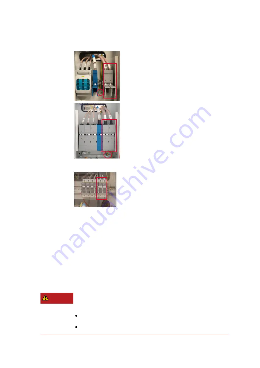
Connection of DC LV load lines (SL1201
–
SL1203)
•
Connect to the DC+/DC- terminal strip according to circuit
diagram of the SL1200A
•
From left to right: DC+/DC-
•
Separate bolt for PE
•
Ring cable lug connections
•
Tightening torque: see circuit diagram
Connection of DC HV load lines (SL1212, SL1213)
•
Connection according to circuit diagram of the SL1200A
•
From left to right: DC+/DC-
•
Separate bolt for PE
•
Ring cable lug connections
•
Tightening torque: see circuit diagram
Connecting sense lines
Connection of DC sense lines, HV + LV
•
Connect to the fuses according to circuit diagram
•
Measure DUT voltage Usense
•
From left to right: DC+/DC-
•
Wire end ferrules connections
Using an emulator adapter with a Scienlab Charging Discovery System
If the SL1200A Scienlab Regenerative AC Emulator is used together with a
SL1040A Scienlab Charging Discovery System for charging technology
application, instead of load and sense lines, an emulator adapter is con-
nected to the Scienlab Regenerative AC Emulator, which is permanently
installed with the output box and no connection inside the outbox is
needed.
Connecting an emulator adapter
In case the emulator adapter is included individually as a component of
the in the scope of delivery, the following installation description must be
observed.
Danger to life due to high voltages.
Some components are still supplied with voltage after switching off (wiring color
orange).
Before installation and maintenance work, turn off and lock out all external
voltage supplies.
Only disconnect or establish electrical connections in a voltage-free condition
DANGER
Summary of Contents for SL1200A Series
Page 2: ......


