


Introduction
1
Keysight J7211A/B/C Operating and Service Manual
13
J7211A/B/C Front and Rear Panels at a Glance
This section briefly explains the functions of front panel keys of J7211A/B/C.
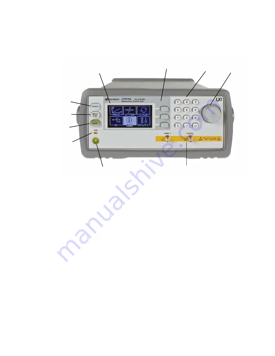
Figure 1-1
J7211A/B/C front panel features
1 LCD screen.
This is a window which shows operating selections for front panel operation.
2 Softkeys.
These unmarked keys are referred to by the text on display next to them.
3 Keypads.
These keys are used to enter numbers e.g. attenuation values, step size, number of
cycles and dwell time.
4 Rotary knob.
Turn this knob to scroll between the submenus on display. This knob also serves
as alternative option for keypads.
5 Connectors.
Type N (f)/SMA (f)/3.5 mm (f) connectors for connection to subsequent device
under test or instruments. Refer J7211A/B/C’s connectors for more details.
6 On/Standby.
Press this key to switch between on and standby. When power is supplied, the
background LED is red. Pressing the key once, boots up attenuation control unit and the
background LED turns to green.
7 LAN.
This is an indicator which tells whether LAN connection is setup or otherwise. Green light
means LAN connection is established.
8 Local.
Press this key to control the attenuation control unit from front panel when it is operating
via remote interfaces. Green light means local operation is in used.
9 Menu/Enter.
Press this key to select the highlighted parameter or select the highlighted field or
go back to main menu.
10 Relative.
Press this key to operate relative attenuation step function.
1
2
3
4
5
6
8
7
9
10


