


111
www.keyestudio.com
The 38K infrared carrier signal
emitted by remote controller is
encoded by the encoding chip
in the remote controller. It is
composed of a section of pilot
code, user code, user inverse
code, data code, and data inverse code. The time interval of the
pulse is used to distinguish whether it is a 0 or 1 signal and the
encoding is made up of these 0, 1 signals.
The user code of the same remote control is unchanged. The data
code can distinguish the key.
When the remote control button is pressed, the remote control
sends out an infrared carrier signal. When the IR receiver receives
the signal, the program will decode the carrier signal and
determines which key is pressed. The MCU decodes the received 01
signal, thereby judging what key is pressed by the remote control.
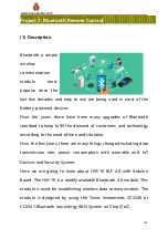
Infrared receiver we use is an infrared receiver module. Mainly
composed of an infrared receiver head, it is a device that integrates
reception, amplification, and demodulation. Its internal IC has
completed demodulation, and can achieve from infrared reception
to output and be compatible with TTL signals. Additionally, it is
suitable for infrared remote control and infrared data transmission.
The infrared receiving module made by the receiver has only three
Summary of Contents for Ks0428
Page 21: ...21 www keyestudio com...
Page 24: ...24 www keyestudio com...
Page 27: ...27 www keyestudio com...
Page 29: ...29 www keyestudio com Step 6 Install Sensors and Boards...
Page 31: ...31 www keyestudio com...
Page 32: ...32 www keyestudio com Step 7 Hook up Guide...
Page 33: ...33 www keyestudio com...
Page 34: ...34 www keyestudio com...
Page 35: ...35 www keyestudio com Step 8 Wire Up LED Panel...
Page 37: ...37 www keyestudio com...
Page 38: ...38 www keyestudio com...
Page 39: ...39 www keyestudio com...
Page 40: ...40 www keyestudio com...
Page 41: ...41 www keyestudio com...
Page 42: ...42 www keyestudio com...
Page 54: ...54 www keyestudio com...
Page 58: ...58 www keyestudio com 5 Arduino IDE Setting Click icon open Arduino IDE...
Page 63: ...63 www keyestudio com Click to start compiling the program check errors...
Page 72: ...72 www keyestudio com Connection Diagram Seen from the above diagram LED is linked with D2...
Page 103: ...103 www keyestudio com 5 Connection Diagram...
Page 126: ...126 www keyestudio com 8 Click Read Notify WriteWithoutResponse to enter the following page...
Page 172: ...172 www keyestudio com 2 Flow chart 3 Connection Diagram...
Page 182: ...182 www keyestudio com 2 Flow chart 3 Connection Diagram...
Page 210: ...210 www keyestudio com 3 Connection Diagram...
Page 223: ...223 www keyestudio com Attention Confirm that every component is connected...
Page 225: ...225 www keyestudio com Servo Motor Brown Wire Gnd G Red Wire 5v V Orange Wire 9...
Page 227: ...227 www keyestudio com IR Receiver Module Sensor Shield G GND V VCC S A0...


