


2
Connections, Buttons and LEDs
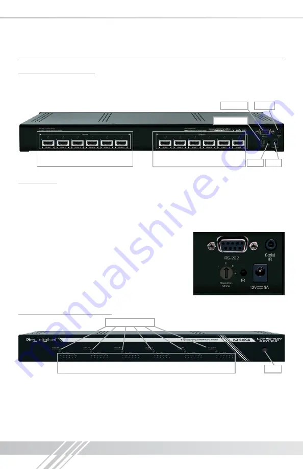
Rear Panel Connections:
All connections to the KD-4x8CS, KD-6x6CS, KD-8x4CS & KD-8x8CS are found on the rear
panel of the units. Refer to the illustrations below for port assignments while making connections.
Power
Serial IR
IR Eye
Operation Mode
RS-232 Port
HDMI Inputs & LEDs
HDMI Outputs & LEDs
Connections
›
HDMI Inputs:
The HDMI Inputs are located on the left side of the back panel. The Inputs have a
blue LED that will illuminate when a source is connected and synced.
›
HDMI Outputs:
The HDMI Outputs are located on the right side of the back panel. The Outputs
have a blue LED that will illuminate when a output device is connected and synced.
›
The
RS-232, Serial IR, Optical IR Sensor, Operation Mode Switch and Power connections
are located on the right side of the back panel.
›
The Operation Mode switch is used to update the unit’s
firmware, which is done using the DB9/RS-232 port. The
firmware version as well as all RS-232 commands is available
through the RS-232 command ‘H’. A detailed list of RS-232
commands is available later in this guide.
›
If newer firmware is made available, complete updating
instructions will be included with it. Check the Key Digital
website for any firmware updates.
Front Panel Buttons and LEDs
Output Select Buttons
IR Eye
Input LEDs
›
There are 4/6/8 Output buttons along the front panel.
›
Pressing an output button will select the next HDMI input.
›
A blue LED will indicate which Input has been selected for each Output.
›
There is also an Optical IR window located on the right side of the front panel for IR remote
control signals.
Summary of Contents for KD-4x8CS Champion
Page 14: ...12 Installation Notes...
Page 15: ...13...


