Key Automation CT202 Instructions And Warnings For Installation And Use Download Page 9

21

EN

UP

SS

DOWN

MENU

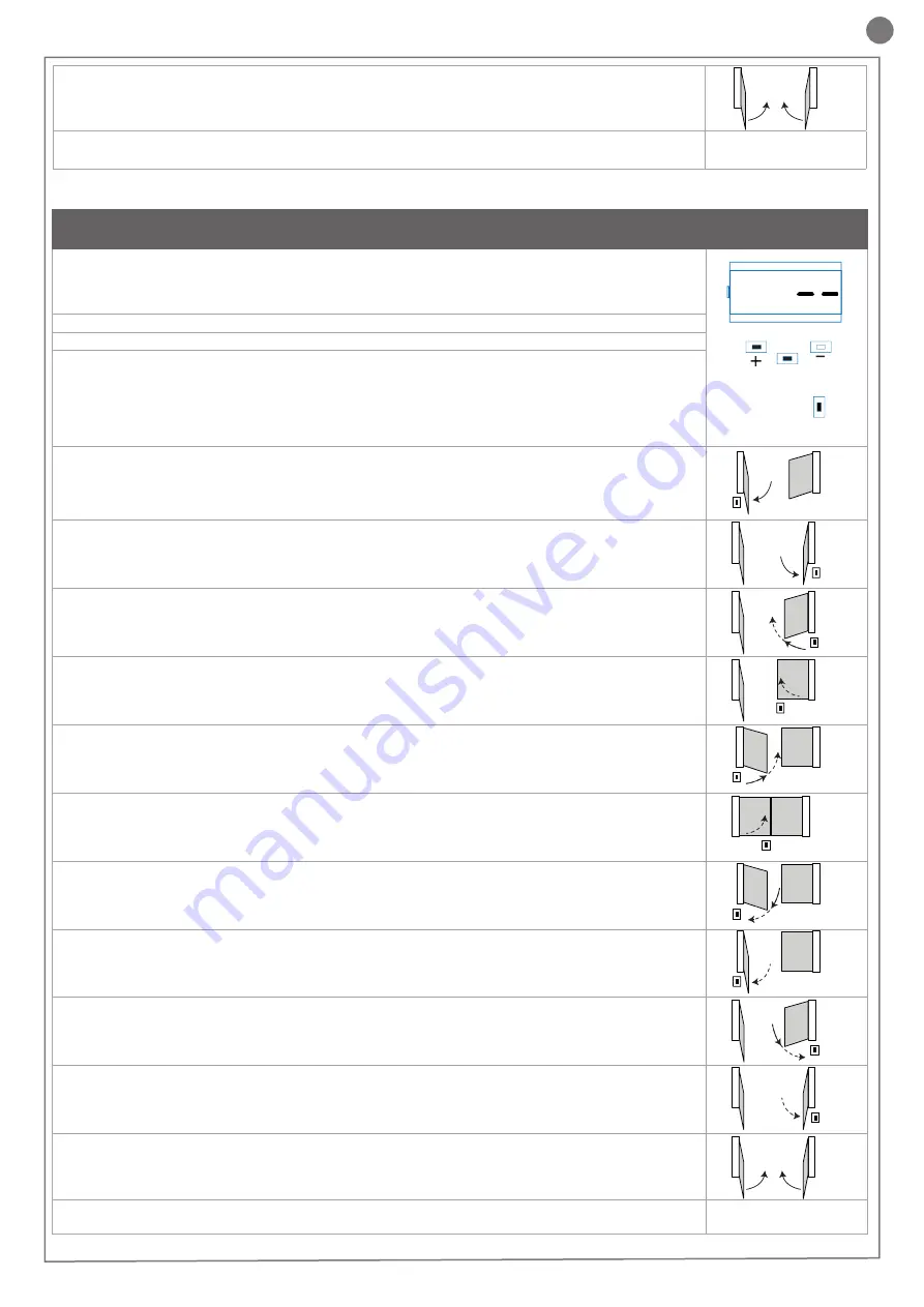
AUTOLEARNING OF THE TRAVEL STROKE AND MAIN PARAMETERS, WITH 

CUSTOMISED DECELERATIONS

Deceleration intervals can be personalised by the user, according to the procedure below.

1. 

CAUTION! check that mechanical end stops (compulsory) are present and secure. The motors must 

always reach the mechanical end stop

2. Move the gate manually to mid-travel.
3. 

CAUTION: enter the main menu to set the parameter 

LSI

 = 

p

 as per the table in paragraph 4.4

4. Press the pushbuttons UP + and MENU at the same time for at least 5 seconds until 

LOP

 is displayed, then 

(if necessary) press DOWN (see figure). 

Ensure that motor M1 opens first; otherwise, press DOWN -, turn the power off and invert connections M1 and 

M2. Repeat the procedure from step 4.

If the first manoeuvre is NOT opening, press DOWN - to stop the self-learning process. Then press SS to 

restart acquisition: the leaf resumes movement in the correct direction. 
5. Motor M1 opens at low speed until it reaches the mechanical opening end stop. 

At precisely the time of reaching the mechanical opening end stop, press the SS  command. 

Motor M2 starts automatically in opening mode. If motor M2 moves in closing, stop by pressing DOWN - and 

resume movement using SS (the leaf resumes movement in the correct direction)

6. Motor M2 opens at low speed. 

At precisely the time of reaching the mechanical opening end stop

After a couple of seconds, motor M2 starts automatically in closing at full speed.

7. 

On reaching the point where motor M2 closing deceleration is required, press SS

. M2 motor move-

ment continues at low speed.

8. 

Precisely when motor M2 reaches the closed position, press the SS command

. Motor M2 stops and 

motor M1 starts in closing.

9. 

On reaching the point where motor M1 closing deceleration is required, press SS

. M1 motor move-

ment continues at low speed.

10. 

Precisely when motor M1 reaches the closed position, press the SS command

. Motor M1 stops and 

restarts in opening.

11. 

On reaching the point where motor M1 opening deceleration is required, press SS

. M1 motor move-

ment continues at low speed.

12. 

Precisely when motor M1 reaches the open position, press the SS command

. Motor M1 stops and 

motor M2 starts in opening.

13. 

On reaching the point where motor M2 opening deceleration is required, press SS

. M2 motor move-

ment continues at low speed. 

14. 

Precisely when motor M2 reaches the open position, press the SS command

. Motor M2 stops.

15. M1 and M2 resume closing according to the offset parameter entered in the menu, i.e. the gate closes 

automatically according to the set travel.

16. Run a number of opening, closing and stop manoeuvres, to check that the system is stable and there are 

no assembly defects.

All main parameters are configured as default by the control unit. To personalise installation, go to the next step in paragraph 4.4.

10. Motors M1 and M2 resume closing according to the leaf offset values set in the menu, i.e. the gate closes 

automatically according to the set travel.

11. Run a number of opening, closing and stop manoeuvres, to check that the system is stable and there are 

no assembly defects.

All main parameters are configured as default by the control unit. To 

personalise installation, go to the next step in paragraph 4.4. If torque 

is not sufficient to move the leaf, delete the deceleration intervals from 

the menu [

LSI

=0].

10

M1

M2

15

M1

M2

5

M1

M2

SS

6

M1

M2

SS

7

M1

M2

SS

8

M1

M2

SS

9

M1

M2

SS

10

M2

SS

M1

11

M1

M2

SS

12

M1

M2

SS

13

M1

M2

SS

14

M1

M2

SS

Summary of Contents for CT202

Page 1: ...para dois motores 230 Vac 120 Vac para portões de batente Centrala dla dwóch silników 230 Vac 120 Vac do bram skrzydłowych CT202 Istruzioni ed avvertenze per l installazione e l uso Instructions and warnings for installation and use Instrucciones y advertencias para su instalación y uso Anleitungen und Hinweise zu Installation und Einsatz Instruções e advertências para a instalação e utilização In...

Page 2: ... Product Electric connections Display during normal operation Autolearning of the travel stroke Customising the system BASIC MENU Connecting the radio receiver Testing and commissioning Testing Commissioning Further details ADVANCED MENU Instructions and warnings for the final user EC declaration of conformity pag 15 pag 16 pag 16 pag 16 pag 16 pag 17 pag 17 pag 18 pag 18 pag 19 pag 20 pag 22 pag ...

Page 3: ...e with the following safety precautions never make any modifications to part of the automation system other than those specified in this manual Operations of this type can only lead to malfunctions The manufacturer declines all liability for damage caused by unauthorised modifications to products do not allow parts of the automation system to be immersed in water or other liquids During installati...

Page 4: ... DOWN pushbutton 12 SS STEP STEP pushbutton 13 Safety device dip switch 14 F3 Safety fuse for AC accessories electric lock 2 A quick acting 15 F2 Safety fuse for DC accessories 500 mA quick acting 16 F1 Safety fuse for power line 6 3 A quick acting 2 3 Models and technical characteristics CT202 control unit is equipped with a display to enable simple pro gramming and constant monitoring of input s...

Page 5: ...s III overvoltage ensure that all the material used for installation complies with the relevant regulatory standards The cables used must be suitable for the type of installation for example an H03VV F type cable is recommended for indoor appli cations while H07RN F is suitable for outdoor applications TECHNICAL SPECIFICATIONS Power supply L N 230 Vac 10 15 50 60 Hz 120 Vac 10 15 50 60 Hz Max moto...

Page 6: ...OP Eliminates the need to bridge the terminal board inputs WARNING with the dip switch ON the safety devi ces are disabled 4 1 Electrical connections WARNING Before making the connections ensure that the control unit is not powered up 2 3 4 1 1 2 TX RX NC PH2 2 3 4 1 1 2 TX RX PH1 N L 24 Vdc 24 Vac 24 Vac EL EL GND 24 TX PH EDGE EDGE PH2 PH1 STOP OPEN CLOSE PED SS COM L N UP DOWN MENU SS COURTESY ...

Page 7: ... device the contact can be deactivated at any time cutting out the automation system and disabling all functions including Automatic Closure OPEN OPEN command NO contact between OPEN and COM Contact for the HOLD TO RUN function The gate OPENS as long as the contact is held down CLOSE CLOSE command NO contact between CLOSE and COM Contact for the HOLD TO RUN function The gate CLOSES as long as the ...

Page 8: ...UTION if manual programming of deceleration intervals is required go to the next table 1 CAUTION check that mechanical end stops compulsory are present and secure The motors must always reach the mechanical end stop 2 Move the gate manually to mid travel 3 Press the pushbuttons UP and MENU at the same time for at least 5 seconds until LOP is displayed then if necessary press DOWN see figure Ensure...

Page 9: ...n press the SS command Motor M2 stops and motor M1 starts in closing 9 On reaching the point where motor M1 closing deceleration is required press SS M1 motor move ment continues at low speed 10 Precisely when motor M1 reaches the closed position press the SS command Motor M1 stops and restarts in opening 11 On reaching the point where motor M1 opening deceleration is required press SS M1 motor mo...

Page 10: ...MENU If necessary users may select a BASIC MENU which allows modi fication of the control unit s basic parameters To select the BASIC MENU proceed as described below WARNING to be certain of accessing the NORMAL OPERATION display state the starting point for accessing the BASIC MENU press the MENU key twice n PARAMETERS DESCRIPTION DEFAULT CONFIGURATION MIN MAX UNIT 1 TCL Automatic reclosing time ...

Page 11: ...g its opening travel and automatic closure is disabled to re start operation the user must press the control button or use the transmitter 5 TESTING AND COMMISSIONING THE AUTOMATION SYSTEM 5 1 Testing All system components must be tested following the procedures de scribed in their respective operator s manuals ensure that the recommendations in Chapter 1 Safety Warnings have been complied with ch...

Page 12: ...or proportional flashing 0 0 4 13 tC Y Courtesy light duration 0 0 900 s steps of 10s 14 dE A Hold to run 0 disabled 1 enabled 0 0 1 15 se r Cycle threshold for assistance request On reaching the set threshold the subsequent cycles will be performed with quick flashing only if FPr is active 0 disabled 0 0 100 x 1000 cycles 16 se f Enabled in continuous flashing mode for assistance requests functio...

Page 13: ... or power failures while waiting for the engineer to come or for the power to be restored if your system is not equipped with buffer batteries the door or gate can be used just like any non automated installation To do this the manual release procedure must be carried out manual release and operation first bear in mind that the release procedure can only be carried out with the door or gate statio...

Reviews: