17
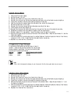
ELEMENT REPLACEMENT
1.
Disconnect the power supply.
2.
Set the furnace on its top.
3.
Remove the 4 feet and 1 screw from the bottom of the unit.
4.
Remove the 2 screws from the thermocouple terminal block and pull the thermocouple straight up.
5.
Inspect the condition of the thermocouple and replace if necessary.
6.
Note the locations the element leads are attached to the control and disconnect.
7.
Set the furnace back onto its base.
8.
Remove the 4 screws connecting the baffle plate assembly to the base.
9.
Lift the element assembly straight up.
10. Remove the 3 screws from the bottom and the 2 screws from the side of the element assembly.
11. Separate the element from the baffle and replace with the new element.
12. Reverse steps 6-10 to reassemble. Insure the screws pass through the insulators.
13. Reinstall the thermocouple and secure the leads to the terminal block. Keep the lead marked “+” and the
black wire together.
14. After reinstalling the thermocouple check the distance between the hearth plate and the tip of the thermo-
couple is 4-1/16 +\-1/16”. Adjust the thermocouple bend as necessary.
15. Replace the 4 feet and the 1 case screw.
Conditioning a New Element
It is essential to preoxidize the element wire at 1050°C
(1922°F). Remove the graphite crucible from the element
chamber before conditioning. Fire your Auto Electro-Melt
according to the following schedule.
Item No.
Voltage
Firing Time at 1050°C/1922°F
31809
120V
3 hours
31808
230V
2 hours
THERMOCOUPLE REPLACEMENT
1.
Disconnect the power supply.
2.
Set the furnace on its top.
3.
Remove the 4 feet and 1 screw from the bottom of the unit.
4.
Remove the 2 screws from the thermocouple terminal block and pull the thermocouple straight up.
5.
Inspect the condition of the thermocouple and replace if necessary.
6.
Reinstall the thermocouple and secure the leads to the terminal block. Keep the lead marked “+” and
the black wire together.
7.
After reinstalling the thermocouple check the distance between the hearth plate and the tip of the thermo-
couple is 4-1/16 +\-1/16”. Adjust the thermocouple bend as necessary.
8.
Replace the 4 feet and the 1 case screw.
Note
If the control temperature display moves downward, the thermocouple leads are reversed.
Summary of Contents for 1258 Series
Page 18: ...18 Exploded View...

