


14
KFA V20-IA-e-1513
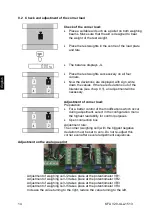
9.2 Check and adjustment of the corner load
Check of the corner load:
•
Place a suitable aid such as a pallet on both weighing
beams. Make sure that the aid is designed to bear
the weight of the test weight.
•
Place the test weights in the centre of the load plate
and tare.
•
The balance displays -0-.
•
Place the test weights successively on all four
corners.
•
Now the deviations are displayed with sign, write
down the values. If there are deviations out of the
tolerances (see chap. 9.1), an adjustment will be
necessary.
Adjustment of corner load:
Preparation:
•
For a better control of the modifications which occur
during adjustment, select in the configuration menu
the highest readability for control purposes.
•
Open connection box
Adjustment rule:
The corner (weighing cell) with the biggest negative
deviation must be set to zero. Do not re-adjust this
corner even after several adjustment sequences.
Adjustment on the analogue print
Adjustment of weighing cell J2 takes place at the potentiometer VR1.
Adjustment of weighing cell J3 takes place at the potentiometer VR2.
Adjustment of weighing cell J4 takes place at the potentiometer VR3.
Adjustment of weighing cell J5 takes place at the potentiometer VR4.
Increase the value turning to the right, reduce the value turning to the left.
Summary of Contents for KFA 1500V20
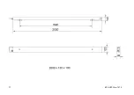
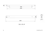
Page 15: ...15 KFA V20 IA e 1513 10 Dimensions ...
Page 16: ...16 KFA V20 IA e 1513 ...
Page 17: ...17 KFA V20 IA e 1513 ...
Page 18: ...18 KFA V20 IA e 1513 ...


