


KEPCO, INC.
131-38 SANFORD AVENUE
FLUSHING, NY. 11355 U.S.A.
TEL (718) 461-7000
FAX (718) 767-1102
http://www.kepcopower.com
email: [email protected]
020316
228-1768
3
c. Overcurrent and Overvoltage protection are set to
the maximum values (see Operator Manual, PAR.
1.1), but are not displayed.
NOTE: Six keys with dual functions are labeled with both a
command and a number. The command label is
referred to when the unit is in command entry
status; the number is referred to when the unit is
in
data entry status.
4. Press
OUTPUT ON/OFF
key to enable the output.
5. Connect a digital voltmeter (DVM) to the (+) and (–) ter-
minals at the rear panel and verify DVM reads 0V.
6. Press
V SET
key. Verify bottom line of LCD reads
Vset
nn
(where nn = voltage setting).
7. Use number keys to enter rated maximum voltage (e.g.
for ATE 25-40DMG, 25V is the rated maximum voltage)
and press
ENTER
. Output voltage will be displayed at
bottom left of LCD.
8. Use
and
keys as necessary to adjust output pre-
cisely to rated maximum voltage. Verify DVM voltage
reading agrees with displayed voltage on LCD within
0.01% of rated maximum. If the LCD reads
VsetMAX=
(value)
, you are entering a value higher than the
maximum voltage setting.
3.3. INSTALLING THE POWER SUPPLY.
ATE-
DMG is intended to be rack-mounted; the four bottom feet
must be removed prior to installation. Refer to PAR. 3.5 for
cooling requirements.
3.4. CONNECTIONS.
Connections are made using the
rear panel terminations (see Figure 4).
3.4.1. LOAD CONNECTION, GENERAL.
Connect the
load between –OUT and +OUT output terminals at the rear
panel (see Figure 4.
Sense connections are required,
either local or remote, must be used; otherwise the
unit will not operate.
See PAR. 3.4.2 for local sensing, see PAR. 3.4.3 for
remote sensing. “Fast” mode is recommended if step
changes in the load are expected: if, for example, the load
is rapidly changing in value, or if the power supply is pro-
grammed with step functions (square wave, pulse, etc.)
and maximum dynamic performance is expected. Set the
unit to “fast” mode by referring to the full Operator Manual
(see PAR. 1.1). Note that ripple in “fast” mode will be higher
than for the default “slow” mode.
Terminals on the barrier strip permit maximum flexibility in
power supply/load interface techniques. The unit is shipped
with several jumper links installed (see Figure 3) for the
default configuration: front panel (local) control of output
voltage, output current and VP crowbar level with the
power supply operating in the “slow” mode. Links on the
barrier strip must be tightened.
CAUTION: Loose links at
the barrier strip will cause malfunction of the power
supply.
To configure the unit to allow remote programming of the
power supply or for “fast mode,” refer to the full Operator
Manual (see PAR. 1.1).
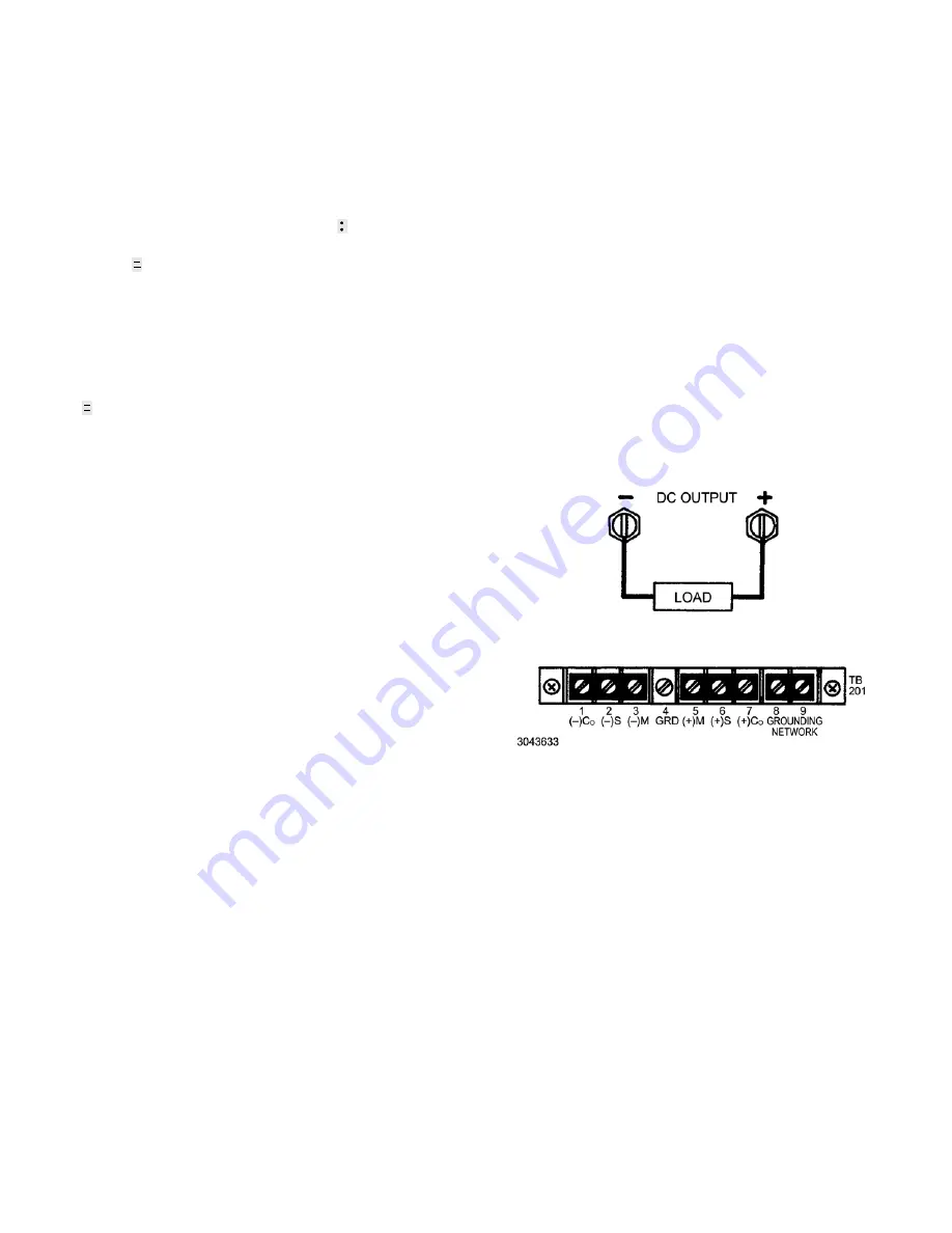
3.4.2. LOAD CONNECTION, LOCAL SENSING.
Figure
3 illustrates load connection using local sensing. Refer to
the full Operator Manual (see PAR. 1.1) for load wire selec-
tion guidelines. The output power leads should be twisted
or tied together to reduce EMI.
FIGURE 3. LOCAL SENSING
3.4.3. LOAD CONNECTION, REMOTE SENSING.
To
avoid excessive output effects at remote loads, remote
error sensing must be used (Kelvin connection). A pair of
wires (twisted to reduce EMI) connected from the sensing
terminals directly to the load will compensate for load wire
voltage drops up to 0.5 volt per wire (refer to Figure 4.
Observe polarities: the negative sensing wire must go to
the negative load wire, and the positive sensing wire goes
to the positive load wire.
If step changes in the load are expected (e.g., the load is
rapidly changing in value and maximum dynamic perfor-
mance is expected directly at the load terminals, refer to
the full Operator Manual (see PAR. 1.1) for alternative
remote sensing connections.
For large capacitive loads with long wire runs, refer to the
full Operator Manual (see PAR. 1.1) for techniques used to
reduce low frequency oscillations observed at the load.


