


7.
MAINTENANCE
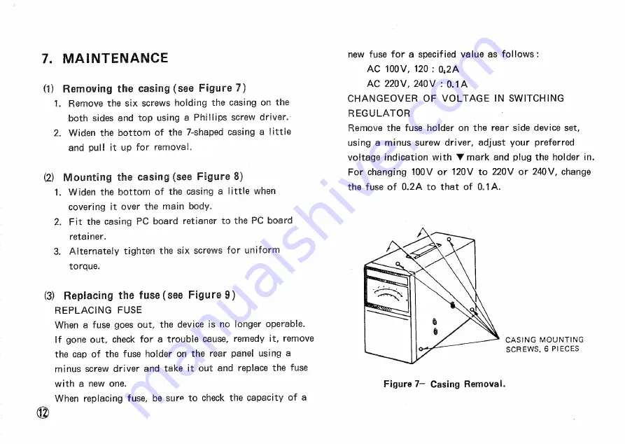
(1)
Removing the
c a s i n g ( s e e F i g u r e 7 )
1. Remove the s i x screws holding the casing on the
both sides and top using a P h i l l i p s screw driver.
2. Widen the b o t t o m of the 7-shaped casing a l i t t l e
and pull it up f o r r e m o v a l .
(2) Mounting the casing (see Figure 8)
1. Widen the bottom of the casing a l i t t l e when
covering it over the main body.
2. F i t the casing P C board retianer to the P C board
retainer.
3. A l t e r n a t e l y tighten the s i x screws f o r u n i f o r m
torque.
(3) Replacing the fuse (see Figure 9)
R E P L A C I N G F U S E
When a fuse goes out, the device is no longer operable.
If gone out, check f o r a trouble cause, remedy it, remove
the cap of the fuse holder on the rear panel using a
minus screw driver and take it out and replace the fuse
w i t h a new one.
When replacing fuse, be sura, to check the c a p a c i t y of a
new fuse f o r a specified value a s f o l l o w s :
A C 100V, 120 : 0 , 2 A
A C 2 2 0 V , 240 V : 0.1 A
C H A N G E O V E R O F V O L T A G E IN S W I T C H I N G
R E G U L A T O R
Remove the fuse holder on the rear side device set,
using a minus surew driver, adjust your preferred
voltage indication w i t h
T
m a r k and plug the holder in.
F o r changing 100V or 120V to 220V or 2 4 0 V , change
the fuse of 0 . 2 A to t h a t of 0.1 A .
Figure 7 - Casing Removal.
C A S I N G MOUNTING
S C R E W S , 6 P I E C E S