background image

36

 EN

ENTER

INPUT SELECTOR

RCV MODE

DIMMER 

°

SLEEP 

°

SOUND

LISTEN MODE 

%

 / 

%

 / 

 / 

@

 / 

#

, ENTER

MULTI CONTROL 

%

 / 

 / 

@

 / 

#

,

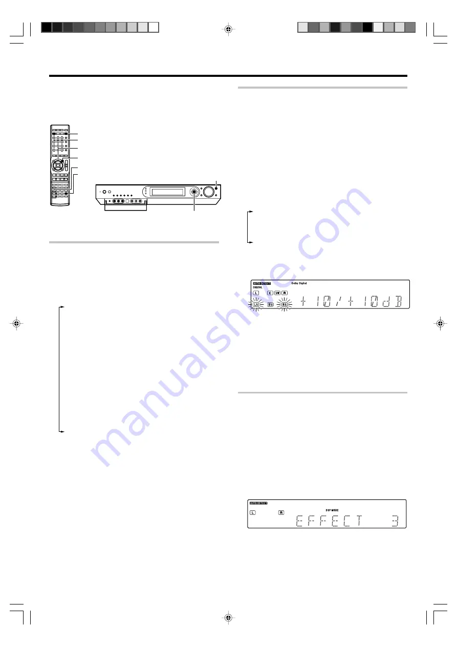
1

Press the RCV MODE key on the remote control unit to

set it to the receiver control mode.

2

Press the SOUND key.

3

Press the MULTI CONTROL 

@

 / 

#

 (or the 

@

 / 

#

 keys) to select

the setting item and press the ENTER.

Note that some items are not displayed in certain modes.

1

"

SP LEVEL

": *1

Adjusting the volume level of each channel

2

"

INPUT

": (Analog mode only)

Input level adjustment

3

"

TONE

": *2

¢

Tone level adjustment

4

"

EFFECT

": (DSP mode only)

DSP effect level adjustment

5

"

DUAL MONO

": *3

Selection between Stereo, Main audio, Sub audio and
Main + Sub audio

6

"

MIDNIGHT

": *4

°

Midnight mode adjustment

7

"

PANORAMA

": *5

Panorama mode ON/OFF

8

"

DIMENSION

": *5

Dimension adjustment

9

"

C WIDTH

": *5

Center width adjustment

0

"

C IMAGE

": *6

°

Center image mode adjustment

*1

The setting in the SOUND mode is temporary. It returns automati-
cally to the original level set in "

Speaker settings

" when the

receiver is turned OFF/ON.

*

*2

PCM stereo and analog stereo mode only.

*3

DOLBY DIGITAL mode only

*4

DOLBY DIGITAL, DTS mode only

*5

Only when the input signal is a 2-channel signal in the DOLBY PRO
LOGIC 

II

x MUSIC or DOLBY PRO LOGIC 

II

 MUSIC mode.

*6

Only when the input signal is a 2-channel signal in the DTS

NEO:6 MUSIC mode.

4

Use the MULTI CONTROL 

%

 / 

 (or the 

%

 / 

 keys) to

adjust the setting as desired.

÷

The adjustment item is displayed for approximately 20 seconds.

5

Press the SOUND key again to return to the input indication.

You can make further adjustments to the sound while listening to
playback in the surround mode.

÷

The mode using the 

SOUND

 key is defeated when the REC MODE is

ON.

§

Adjusting the sound

Adjusting the volume level of each channel

The volume levels of the center speaker, subwoofer, surround speaker

and surround back speaker channels can be adjusted during playback.

1

Press the RCV MODE key on the remote control unit to

set it to the receiver control mode.

2

Press the SOUND key.

3

Use the MULTI CONTROL 

@

 / 

#

 (or the 

@

 / 

#

 keys) to

select "SP LEVEL" on setup displays, and press the

ENTER.

4

Use the MULTI CONTROL 

@

 / 

#

 (or the 

@

 / 

#

 keys) to

select the speaker.

1

Subwoofer level adjustment ("

SW

" indicator blinks)

2

Center speaker level adjustment ("

C

" indicator blinks)

3

Surround speaker level adjustment ("

LS

", "

RS

" indicator

blinks)

4

Surround back speaker level adjustment ("

LB

", "

RB

" or

"

BS

" indicator blinks)

5

Use the MULTI CONTROL 

%

 / 

 (or the 

%

 / 

 keys) to

adjust the speaker volume level.

÷

The level of each speaker channel can be adjusted in 1 dB

steps between -10 dB and +10 dB.

6

Repeat steps 

4

 and 

5

 as required.

7

Press the SOUND key again to return to the input

indication.

÷

The setting in the SOUND mode is temporary. It returns automati-

cally to the original level set in "

Speaker settings

" when the

receiver is turned OFF/ON.

*

Adjusting the DSP effect level 

(DSP mode only)

The DSP effect level can be adjusted when the listen mode is a DSP surround

mode "

ARENA

", "

JAZZ CLUB

", "

THEATER

", "

STADIUM

" or "

DISCO

".

1

Press the RCV MODE key on the remote control unit to

set it to the receiver control mode.

2

Press the SOUND key.

3

Use the MULTI CONTROL 

@

 / 

#

 (or the 

@

 / 

#

 keys) to

select  "EFFECT" on setup displays, and press the  ENTER.

4

Use the MULTI CONTROL 

%

 / 

 (or the 

%

 / 

 keys) to

adjust the EFFECT LEVEL.

÷

The DSP effect level can be adjusted in the range between 1 and 5.

5

Press the SOUND key again to return to the input indication.

Convenient functions

Summary of Contents for VRS-7200 - AV Receiver

Page 1: ... control it is important to read the operating instructions and obtain a proper understanding of the remote control and how to switch its operation modes etc Using the remote control without completely understanding its design and how to switch the operation modes may result in incorrect operations Quick Start Reference Please read the following pages so that you can enjoy the surround sound at th...

Page 2: ...ING THE APPLIANCE THE LIGHTNING FLASH WITH ARROWHEAD SYMBOL WITHIN AN EQUILATERAL TRIANGLE IS INTENDED TO ALERT THE USER TO THE PRESENCE OF UNINSULATED DANGEROUS VOLTAGE WITHIN THE PROD UCT S ENCLOSURE THAT MAY BE OF SUFFICIENT MAGNITUDE TO CONSTITUTE A RISK OF ELECTRIC SHOCK TO PERSONS CAUTION TO REDUCE THE RISK OF ELECTRIC SHOCK DO NOT REMOVE COVER OR BACK NO USER SERVICEABLE PARTS INSIDE REFER ...

Page 3: ...eatures True home theater sound This receiver incorporates a wide variety of surround modes to bring you maximum enjoyment from your video software and audio source Select a surround mode according to your equipment or the software you are going to play and enjoy Dolby Digital EX Dolby PRO LOGIC IIx Dolby PRO LOGIC II Dolby Digital DTS ES DTS NEO 6 DTS 96 24 DTS DSP Mode Dolby Virtual Speaker Dolb...

Page 4: ...ations RDS AUTO MEMORY 29 Using the RDS DISP Display key 29 Tuning by Program TYpe PTY search 30 Ambience effects 31 Surround modes 31 Virtual modes 33 Surround play 34 Convenient functions 36 Adjusting the sound 36 Display dimmer adjustment 38 Sleep timer 38 Basic remote control operations for other components 39 Registering setup codes for other components 39 Searching for your code 39 Checking ...

Page 5: ...o adjust the receiver volume Display Speaker selection indicators Input channel indicators The Input channel indicators lights up to indicate the channels contained in the input signal The S indicator lights when the surround component consists of a single channel ACTIVE EQ indicator DUAL SOURCE Input indicator 96 kHz fs indicator Frequency display Input display Preset channel display Listen mode ...

Page 6: ... STANDBY 3 SLEEP key Use to set the Sleep timer 4 INPUT MODE key Use to switch between the full auto digital and analog input 8 5 Numeric keys Use to selection of preset radio stations Use to operate other components 6 100 key Use to operate other components INFO key Use to operate other components 7 AUDIO key Use to operate the DVD component 8 SUBTITLE key Use to operate the DVD component 9 SETUP...

Page 7: ...o operate the multi CD player LAST key Use to operate other components PAGE fi keys Use to operate the DVD component For Europe and Australia RDS DISP key ª Use to receive RDS broadcast PTY key º Use for PTY search ANGLE key Use to operate the DVD component ª MUTE key Use to temporarily mute the sound º SOUND key Use to adjust the sound quality and the ambience effects fl MENU key Use to operate oth...

Page 8: ...lights up 2 D MANUAL Fixed to digital input DIGITAL indicator lights up 3 ANALOG Fixed to analog input AUTO DETECT DIGITAL indicator goes off Can not be selected for DTS playback Auto detect In F AUTO FULL AUTO mode AUTO DETECT indicator light up the receiver detects the digital or analog input signals automatically The receiver will select the input mode and listen ing mode automatically during p...

Page 9: ...O LINE OUT or MIX LINE OUT Audio cord S VIDEO OUT S VIDEO cord DVD player COMPOSITE VIDEO IN Yellow RCA pin cord COMPONENT VIDEO IN Monitor TV Digital audio connections are required when playing multi channel signals such as the Dolby Digital and DTS signals To play the DVD player connected in this page select the DVD input selector If you have connected a DVD player to the receiver with digital c...

Page 10: ...IDEO 2 DVD ASSIGNABLE INPUT COMPONENT VIDEO HDD Recorder DVD Recorder Satellite Receivers Game Player with component jacks Connecting video components COMPONENT VIDEO Monitor TV with component jacks DVD player with component jacks Y OUT CB OUT CR OUT Y OUT CB OUT CR OUT CB IN Y IN CR IN If you have connected the receiver to a video component with COMPONENT jacks you can get a better picture qualit...

Page 11: ...CD digital signals If you have connected components with digital audio output to the receiver with digital connection be sure to read the Input mode settings Re assignment of rear panel jacks section carefully 8 DTS disclaimer clause When playing DTS encoded discs excessive noise will be exhib ited from the analog stereo outputs of the CD or DVD player To enjoy DTS Digital Surround playback this u...

Page 12: ...cted properly can be confirmed by outputting the test tone and checking if each speaker channel outputs audio For details see Speaker settings Step 6 Adjust the speaker volume level CAUTION Make sure that the power cord plug is disconnected from the AC wall outlet before proceeding to speaker cord connections If the conductor wires on the extremity of speaker cord are untwisted there is a risk of ...

Page 13: ...can divide those signals between the available speakers in the speaker settings steps to obtain the best possible surround repro duction from the speakers you have available Setting up the system Speaker impedance After confirming the speaker impedance indications printed on the rear panel of the receiver connect speakers with matching imped ance ratings Using speakers with a rated impedance other...

Page 14: ...nnected to an external power amplifier If you want to connect surround back speakers to these jacks be always sure to connect two surround back speakers for the left and right Connecting to the GAME jacks FRONT AUX jacks If you use a component that you do not usually connect to the receiver such as a portable video camera connect it to the GAME or FRONT AUX jacks on the front panel of the receiver...

Page 15: ...ver Insert two AAA size R03 batteries as indicated by the polarity markings Remote control operation When the STANDBY indicator is lit the power turns ON when you press the RECEIVER on the remote control When the power comes ON press the key you want to operate When pressing more than one remote control key successively press the keys securely by leaving an interval of 1 second or more between key...

Page 16: ...ect press the MULTI CONTROL fi to select OK and press the ENTER Now the speaker setup is complete Select CANCEL to return to the status before setup More detailed settings such as the volume level of each speaker and distance to each speaker are also available If you connect KENWOOD speaker system Connection of speakers Connection of TV monitor Connection of DVD player Composite video connection Co...

Page 17: ...he operation also refer to the instruction manual for your DVD player You can select various listen modes to enjoy surround playback of various kinds of video software Example 5 1 ch Surround System 3 After completing the setup press the ENTER If your selection is correct press the MULTI CONTROL fi to select OK and press the ENTER Now the speaker setup is complete Select CANCEL to return to the sta...

Page 18: ...5 1CH if you use speaker system KS 8200HT 7 CUSTOM Select to set up the speakers according to the speaker system in use Speaker setup is required every time after the speaker system is changed 8 EXIT Press the ENTER again to return to the main setup displays Model availability may differ depending on the country and sales area When the 5 1 channel speaker system configuration is used or the speake...

Page 19: ... to the receiver 2 CNTR NML An average size center speaker is connected to the receiver 3 CNTR OFF When no center speaker is connected CNTR LRG cannot be selected when the front speakers have been set to FRNT NML 6 Use the MULTI CONTROL or the key to ac cept the setting The surround speaker setting indication SURR appears 7 Use the MULTI CONTROL fi or the fi keys to select the appropriate surround s...

Page 20: ...setup displays Select CANCEL and press the ENTER to return to the status before setup 6Adjust the speaker volume level From your usual listening position adjust the volume levels The volume levels from each speaker should be the same In steps 6 indications appear only for the selected channels of the speakers that require adjusting 1 Use the MULTI CONTROL or the keys to select SP LEVEL on setup di...

Page 21: ...m adjustable in 1 foot 0 3 m increments 4 Repeat steps 3 to input the distance for each of the speakers 5 Press the ENTER again to return to the main setup displays Indication in meters 8Adjust the LFE LEVEL Low Frequency Effects level Adjust the level of the low frequency fields effect LFE signal which is the signal used exclusively for giving the field effect of bass tone in the Dolby Digital or...

Page 22: ...NTER 3 Use the MULTI CONTROL or the keys to select DIGITAL or COMPONENT andpresstheENTER 1 DIGITAL Select to change the assignment of the digital audio input jacks of the receiver 2 COMPONENT Select to change the assignment of the component video input jacks of the receiver 3 EXIT Press the ENTER again to return to the main setup displays Inputselectorposition fi 1 DVD 2 V2 3 V1 4 AUX When the DIGI...

Page 23: ...d a component connected to the COAX 1 DVD COAX 2 VIDEO 2 OPT 1 VIDEO 1 OPT 2 AUX or DIGITAL IN OPTICAL jacks make sure that the input mode setting is correct for the type of audio signal to be used 8 ON STANDBY RECEIVER RCV MODE INPUT MODE 1Press the INPUT SELECTOR key or the input selector keys DVD VIDEO 1 VIDEO 2 AUX F AUX GAME TUNER to select the source you want to listen to 1 Tuner FM AM broad...

Page 24: ...ob or the VOLUME fi keys to adjust the volume Playing difference sources through speakers and headphones DUAL SOURCE function While you enjoy audio listening through the speakers another person can enjoy another source audio video through headphones by connecting the source to the GAME or FRONT AUX jacks 1 Connect headphones to the PHONES jack 2 Press the DUAL SOURCE ON OFF key to switch the DUAL S...

Page 25: ...e ACTIVE EQ indicator lights up Effective when playing a game 4 EQ OFF The ACTIVE EQ indicator goes off The ACTIVE EQ function is turned OFF The ACTIVE EQ function is not available in when the REC MODE or virtual mode is ON Muting the sound The MUTE key lets you mute the sound of the speakers or headphones Press the MUTE key To cancel Press the MUTE key again so that the MUTE indicator goes off MU...

Page 26: ...i channel source such as the Dolby Digital or DTS input signal is recorded in REC mode the multi channel signal in the current surround mode can be recorded down mixed to 2 channel DTS 5 1 MUSIC DISC DTS CD cannot be recorded INPUT SELECTOR SETUP 1 Use the INPUT SELECTOR key or the input selector keys to select the source DVD VIDEO 2 AUX or GAME you want to record 2 Put the component connected to ...

Page 27: ...fi or the fi keys to select the desired station Presetting radio stations AUTO MONO BAND INPUT SELECTOR MULTI CONTROL fi ENTER Collective presetting of stations For U S A and Canada 1Use the INPUT SELECTOR key or the TUNER key to select the tuner 2Use the BAND key to select he broadcast band to FM 3Press and hold the ENTER for more than 2 seconds The AUTO display and PRESET display appear alternately...

Page 28: ... the original display and start again Receiving preset stations INPUT SELECTOR P CALL 4 MULTI CONTROL TUNER 1Use the INPUT SELECTOR key or the TUNER key to select tune as the source 2Use the MULTI CONTROL or the P CALL 4 keys to select the desired station Each time you push the Joystick another preset station is received in order Pushing the Joystick to does the following Pushing the Joystick to d...

Page 29: ...fewer than 40 RDS stations have been stored in the preset memory regular FM stations will be stored in the remaining places Radio Text function Displays the radio text data transmitted by some RDS stations when you press the RDS DISP display key There is NO RT if no text data is transmitted The RDS indicator lights up when an RDS broadcast signal is received Note Some functions and function names ...

Page 30: ...Lights up Using RDS Radio Data System For Europe and Australia 1Press the PTY key to activate the PTY search mode When an RDS broadcast is received the program type is shown on the display If no PTY data is available or if the station is not an RDS station NONE is displayed 2While the PTY indicator is lit use the fi keys or the TUNING 1 keys to select the program type of your choice Program type ta...

Page 31: ... decoder that derives three surround channels from the two in the original recording This is achieved by using three different surround signals Left Surround Right Surround and Back Surround each driving its own array of speakers Think of it as adding a center channel for the rear speakers which give more diffuse and natural surround effect even if you wanted the ability to completely encircle the...

Page 32: ...ext time you watch a concert or sporting event What s DSP DSP stands for Digital Signal Processor The way a sound is heard in an actual environment depends on a variety of different factors One of the most important is reverberation the act of decaying elements of sound echoing in various places The DSP modes produce the feeling of presence by using the DSP to create reverberation without spoiling...

Page 33: ...olby Headphone simulates a virtual room and include its acoustic characteristics in the left and right headphone signals As a result the listener can hear the same components as in speaker listening through the left and right years and therefore feel as if the sound source is located on the front of the listener Ambience effects How to set the Dolby Virtual Speaker mode when not using headphones P...

Page 34: ...EX DOLBY DIGITAL EX surround 3 DOLBY D PLIIx MOVIE DOLBY DIGITAL surround DOLBY PRO LOGIC IIx surround MOVIE mode 1 4 DOLBY D PLIIx MUSIC DOLBY DIGITAL surround DOLBY PRO LOGIC IIx surround MUSIC mode 5 STEREO Stereo playback 2 1 Can be selected only when two surround back speakers are con nected 2 In Dolby Virtual Speaker and Dolby Headphone modes the Dolby Digital signal input cannot be listened...

Page 35: ... 1 Cannot be selected in Dolby Virtual Speaker and Dolby Headphone modes 2 The sound field can be adjusted as desired using the PANORAMA DIMENSION and CENTER WIDTH modes 3 Cannot be selected in Dolby Virtual Speaker modes 4 The sound field can be adjusted as desired using the CENTER IMAGE modes 5 Cannot be selected in Dolby Virtual Speaker and Dolby Headphone modes or with a 96 kHz linear PCM sign...

Page 36: ... SOUND key is defeated when the REC MODE is ON Adjusting the sound Adjusting the volume level of each channel The volume levels of the center speaker subwoofer surround speaker and surround back speaker channels can be adjusted during playback 1 Press the RCV MODE key on the remote control unit to set it to the receiver control mode 2 Press the SOUND key 3 Use the MULTI CONTROL or the keys to sele...

Page 37: ...cation Dimension mode Only when the input signal is a 2 channel signal in the DOLBY PRO LOGIC IIx MUSIC or DOLBY PRO LOGIC II MUSIC mode When listening to music with certain recordings you will also be able to achieve a suitable balance from all the speakers by adjusting the dimension mode 1 Press the RCV MODE key on the remote control unit to set it to the receiver control mode 2 Press the SOUND ...

Page 38: ... can be selected only if DVD VIDEO 1 VIDEO 2 AUX or GAME is selected as the source and the listen mode is set to DOLBY DIGITAL or DTS 4 Use the MULTI CONTROL fi or the fi keys to select the MIDNIGHT2 MIDNIGHT1 or OFF setting 1 MIDNIGHT2 Large effect Suitable for late night use 2 MIDNIGHT1 Medium effect 3 OFF The adjustment item is displayed for approximately 20 sec onds Some DOLBY DIGITAL or DTS sof...

Page 39: ...rned ON or OFF If the component is a VCR turn the VCR ON and load a video tape and perform an operation such as playback The VCR should function as controlled if its setup code is registered properly If the component does not function properly If more than one setup code is listed for the component try registering another setup code by performing steps 3 to 5 Repeat steps 1 to 5 above to register ...

Page 40: ... and system component types see the table on the previous page To restore the original component type assignment of an input selector key press that input selector key twice after entering 9 9 2 It is not possible to register a component in the TUNER key Examples of key re assignment and the order of pressing the keys Registration of a DVD player in the VIDEO 1 key To change the VIDEO 1 key to the...

Page 41: ...0 Viewsonic 1329 Video Accessories Manufacturer Setup Codes AlphaStar 0772 Chaparral 0216 Crossdigital 1109 DirecTV 0392 0566 0639 1639 1142 0247 0749 1749 0724 0819 1856 1076 1109 0099 1442 1108 1414 1640 Dish Network 1005 0775 1775 System Dishpro 1005 0775 1775 Echostar 1005 0775 1775 Expressvu 0775 1775 GE 0566 General Instrument 0869 GOI 0775 1775 Hisense 1535 Hitachi 0819 1250 HTS 0775 1775 H...

Page 42: ...1 1963 Symphonic 0180 0171 Tandy 0093 Tatung 1756 Technics 0250 0051 Techwood 0051 Teknika 0054 0180 0150 0060 0092 Telefunken 0702 TMK 0178 TNCi 0017 Toshiba 0154 1256 0156 0060 1935 1704 1945 1356 1936 TVS 0463 V Inc 1756 0885 Vector Research 0030 Victor 0053 Vidikron 0054 Vidtech 0178 Viewsonic 1755 0885 Wards 0054 0030 0178 Waycon 0156 Westinghouse 0889 White 0463 0623 Westinghouse Yamaha 0030...

Page 43: ...0039 0033 0000 0209 ZT Group 1972 VCR Continued Manufacturer Setup Codes ABS 1972 Alienware 1972 CyberPower 1972 Dell 1972 Gateway 1972 Hewlett Packard 1972 Howard Computers 1972 HP 1972 iBUYPOWER 1972 Media Center PC 1972 Microsoft 1972 Mind 1972 Northgate 1972 Panasonic 0616 Philips 0739 0618 ReplayTV 0616 Sonic Blue 0616 Sony 1972 0636 Systemax 1972 Tagar Systems 1972 Tivo 0618 0739 0636 Toshib...

Page 44: ... Manufacturer Setup Codes sat 1300 Sky 1334 ABsat 0832 0123 ADB 0642 1259 Aegir 0520 AGS 0710 Akai 0200 Alba 0455 Aldes 0520 Allsat 0200 1043 1017 Allvision 1412 1334 Ampere 0132 Amstrad 0847 1175 0132 0243 1113 0795 0882 0345 0863 AntSat 1083 1017 Apollo 0455 Arcon 1205 1075 1043 Arion 1205 Armstrong 0243 Arnion 1300 Asat 0200 ASCI 1334 AssCom 0853 AST 0321 Astacom 0710 Aston 1261 0142 Astra 0607...

Page 45: ...n 0132 0607 1294 0299 0867 0794 Luxor 0345 Manata 0132 0710 Manhattan 0455 1083 1017 0520 Marantz 0200 Mascom 0520 Maspro 0173 Matsui 0173 1284 0710 Max 0607 Maximum 1075 MDS 1225 Mediacom 1206 Mediamarkt 0243 MediaSat 0853 0292 Medion 0132 1075 1043 1412 0299 1334 Mega 0200 Metronic 0243 1215 1205 0520 1334 Metz 0173 Micro 1294 0607 Micromaxx 0299 Microstar 1075 Mitsubishi 0455 Morgan s 0200 0132...

Page 46: ...370 Amstrad 0037 1037 0264 0218 0433 0412 0648 0371 0516 0009 Anam 0009 Anglo 0264 0009 Anitech 0037 0282 0009 Ansonic 0668 0370 0104 0009 Apollo 0473 Arc En Ciel 0196 0109 0198 Ardem 0037 0714 Aristona 0556 0037 0012 Arthur Martin 0163 ASA 0104 0087 0070 Asberg 0037 Asora 0009 Astra 0037 Asuka 0264 0218 ATD 0698 Atlantic 0037 0259 0206 Atori 0009 Auchan 0163 Audiosonic 0037 0714 0486 0715 0264 03...

Page 47: ...2 Fujitsu General 0206 0009 Funai 0668 0264 0294 Futronic 0264 Galaxi 0037 Galaxis 0037 0370 GBC 0218 0009 0374 GE 0625 0560 0093 0282 0178 GEC 0037 0361 0163 0072 0516 Geloso 0009 0374 General Technic 0009 Genesis 0037 0009 Genexxa 0037 0218 0163 0412 0009 Goldfunk 0668 GoldStar 0037 0714 0715 0606 0361 0178 0377 0163 0109 0247 Gooding 0487 Goodmans 0556 0037 0714 0560 0668 0634 1909 1037 0487 02...

Page 48: ... 0808 0512 Megas 0610 MEI 1037 Melectronic 0037 0714 0634 0104 0346 0512 0247 0480 0009 0661 0163 0374 Memorex 1037 0009 0178 Memphis 0337 Mercury 0037 0009 Metronic 0625 Metz 0037 0668 0587 0746 0447 0367 0087 0535 MGA 0218 0374 0178 Micromaxx 0037 0668 1037 0808 Microstar 0808 Minato 0037 Minerva 0487 0108 0070 0516 0535 Minoka 0037 0412 Mistral Electronics 0193 Mitsubishi 0556 0037 1037 0036 01...

Page 49: ... Seaway 0634 Seelver 1037 SEG 0037 0668 0634 1037 0264 0218 0036 0009 SEI 0037 0206 0163 0516 0087 0294 Sei Sinudyne 0037 0087 0516 0294 0206 Seleco 0264 0259 0371 0206 0346 0163 Sencora 0009 Serino 0610 0455 0093 Sharp 0036 1193 0193 0516 0093 0294 0200 Shintoshi 0037 Shivaki 0037 0178 0443 Shorai 0294 Show 0072 0009 0418 Siarem 0516 0087 Siemens 0037 0195 0200 0535 0328 0327 Siera 0012 Siesta 03...

Page 50: ...cturer Setup Codes Accent 0072 Adyson 0072 Aim 0278 0020 Aiwa 0037 0348 0000 0307 0352 0734 0687 1137 0742 Akai 0037 0348 0642 0352 0315 0106 0240 0020 0041 Akiba 0072 Akura 0072 Alba 0081 0278 0348 0000 0072 0352 0315 0020 Allorgan 0240 Allstar 0081 Ambassador 0020 America Action 0278 Amstrad 0278 0000 0072 1942 Anam 0037 0226 0240 Anam National 0226 Anitech 0072 Ansonic 0000 Aristona 0081 ASA 00...

Page 51: ...0315 0106 LXI 0037 M Electronic 0000 0038 Magnasonic 0278 0593 Magnavox 0081 0000 0642 Magnin 0240 Magnum 0642 Manesth 0081 0072 0045 Marantz 0081 0038 Mark 0278 0000 0020 Master s 0278 Matsui 0278 0348 0352 0742 0687 0240 Mediator 0081 Medion 0348 0642 0352 Melectronic 0037 0000 0038 Memorex 0037 0348 0000 0104 0048 0240 Memphis 0072 Mercury 0020 Metronic 0081 Metz 0081 1562 0037 0226 0195 0836 0...

Page 52: ...o 0722 Tokai 0037 0072 0104 0041 Topline 0348 Toshiba 0081 0384 0352 0045 0043 0432 0742 0041 Totevision 0037 Towada 0072 Tradex 0081 Trakton 0020 Triad 0278 TVA 0020 Uher 0240 Ultravox 0278 Unitech 0240 United 0348 United Quick Star 0278 Universum 0081 0037 0348 0000 0104 0106 0240 0195 1137 Victor 0067 Video Concepts 0045 Video Pro 0020 Video Technic 0000 Videomagic 0037 VideoPro 0020 Videosonic...

Page 53: ...sonic 0490 1908 1907 1910 1909 Panda 0717 Pelican 0731 Philco 0788 0690 Philips 0539 0503 0646 1914 Phonotrend 0699 Pioneer 0571 0525 0631 1902 1900 0638 1965 Plu2 0850 Powerpoint 0872 Prima 0766 Prima Electronic 0766 Prinz 0831 Prism 0705 Proline 0651 1004 0672 Proscan 0522 Prosonic 0699 ProVision 0699 Radionette 0741 Raite 0665 RCA 0522 REC 0490 0766 Red Star 0770 0898 0788 Redstar 0898 Reoc 076...

Page 54: ...0 0705 0788 1153 0783 Schwaiger 0752 Scientific Labs 0768 Scott 0651 1036 0672 SEG 0768 0872 0713 0665 Shanghai 0672 Sharp 0630 0752 Sherwood 0741 0717 Shinco 0717 Silva 0788 0898 Silva Schneider 0831 0898 Simaudio 0885 Singer 0768 0716 0690 0751 Skymaster 0730 0768 Skysonic 0766 Skyworth 0766 Slim Devices 0533 SM Electronic 0730 0768 0690 Smart 0713 0705 Sonashi 0831 0716 Sonic Blue 0783 Sony 057...

Page 55: ...e same as the numeric keys on the original remote 1 Select the input source 2 Press the keys corresponding to the operations you desire Refer to the following sections for details These keys can be used to perform the basic operations of KENWOOD and other manufacturers components which the setup code for each component had been entered beforehand qr DVD player operation keys Skip up 4 Skip down 7 ...

Page 56: ...EP TV SOURCE RECEIVER DISC SKIP LAST INFO AUDIO VOLUME ENTER TUNING SUBTITLE ANGLE MUTE 1 2 3 4 5 6 7 8 9 100 10 0 fi 8 6 1 P CALL CHANNEL 4 7 TUNER DVD BAND AUX F AUX GAME VIDEO1 VIDEO2 AUTO MONO TV INPUT DOLBY VIRTUAL RCV MODE LISTEN MODE STEREO TV VOLUME REMOTE SETUP TV MUTE TV MODE ENTER Cursor up fi Cursor down Cursor left Cursor right MENU SOURCE Source Power TV INPUT TV VOLUME fi TV MUTE SUBTI...

Page 57: ...t a surround mode Adjust the speaker levels using the test tone The protection circuitry is activated because speaker cords are short circuited Disconnect the power cord from the AC wall outlet switch the receiver OFF remove the short circuiting and turn the receiver ON again The protection circuitry is activated because the output power is too high Turn this unit OFF then ON again and reduce the ...

Page 58: ...ces air pollution and lowers utility bills FCC WARNING This equipment may generate or use radio frequency energy Changes or modifications to this equipment may cause harmful interference unless the modifications are expressly approved in the instruction manual The user could lose the authority to operate this equipment if an unauthorized change or modification is made NOTE This equipment has been ...

Page 59: ...IDEO DVD VIDEO 2 Luminance signal 1 Vp p 75 Ω Chrominance signal 0 286 Vp p 75 Ω COMPONENT VIDEO DVD VIDEO 2 Luminance signal 1 Vp p 75 Ω CB CR signal 0 64 Vp p 75 Ω Output level impedance Composite VIDEO 1 MONITOR OUT 1 Vp p 75 Ω S VIDEO MONITOR OUT Luminance signal 1 Vp p 75 Ω Chrominance signal 0 286 Vp p 75 Ω COMPONENT VIDEO MONITOR OUT Luminance signal 1 Vp p 75 Ω CB CR signal 0 64 Vp p 75 Ω ...

Page 60: ...DEO 1 VIDEO 2 FRONT AUX GAME 1 Vp p 75 Ω S VIDEO DVD VIDEO 2 Luminance signal 1 Vp p 75 Ω Chrominance signal 0 286 Vp p 75 Ω COMPONENT VIDEO DVD VIDEO 2 Luminance signal 1 Vp p 75 Ω CB CR signal 0 7 Vp p 75 Ω Output level impedance Composite VIDEO 1 MONITOR OUT 1 Vp p 75 Ω S VIDEO MONITOR OUT Luminance signal 1 Vp p 75 Ω Chrominance signal 0 286 Vp p 75 Ω COMPONENT VIDEO MONITOR OUT Luminance sign...

Reviews: