TK-385
4
5. PC Mode
5-1. Preface
The TK-385 transceiver is programmed by using a personal
computer, programming interface (KPG-36) and programming
software (KPG-62D).
The programming software can be used with an IBM PC or
compatible. Figure 1 shows the setup of an IBM PC for
programming.
5-2. Connection procedure
1. Connect the TK-385 to the personal computer with the
interface cable.
2. When the POWER switch on, user mode can be entered
immediately. When PC sends command the radio enter PC
mode, and “PROGRAM” is displayed on the LCD.
When data transmitting from transceiver, the red LED is
blinking.
When data receiving to transceiver, the green LED is blinking.
Notes:
•
The data stored in the personal computer must match model
type, when it is written into the flash memory.
•
Change the TK-385 to PC mode, then attach the interface
cable.
Mode
Function
User mode
For normal use.
Panel test mode
Used by the dealer to check the
fundamental characteristics.
Panel tuning mode
Used by the dealer to tune the radio.
PC mode
Used for communication between the
radio and PC (IBM compatible).
Data program-
Used to read and write frequency data
ming mode
and other features to and from the radio.
PC test mode
Used to check the radio using the PC.
This feature is included in the FPU.
See panel tuning.
Firmware program-
Used when changing the main
ming mode
program of the flash memory.
3. Panel Test Mode
Setting method refer to ADJUSTMENT.
4. Panel Tuning Mode
Setting method refer to ADJUSTMENT.
2. How to Enter Each Mode
Mode
Operation
User mode
Power ON
Panel test mode
[B]+Power ON
PC mode
Received commands from PC
Panel tuning mode
[Panel test mode]+[A]
Firmware programming mode [A]+Power ON
REALIGNMENT
1. Modes
User mode
Panel test mode
PC mode
Firmware
programming mode
Panel tuning mode
PC test mode
Data programming
mode
PC tuning mode
OPERATING FEATURES / REALIGNMENT
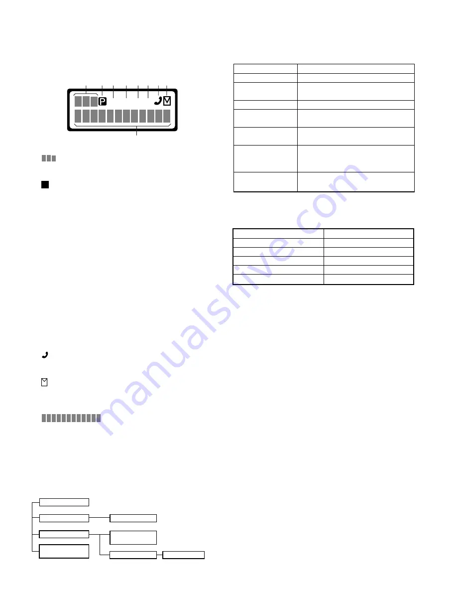
2-4. Display
1
Sub display
displays the strength of received signals.
2
Programming indicator
P
appears while in AUX A or Scrambler is being activated.
3
MON (Monitor) indicator
MON
appears while you are monitoring a channel by pressing
the Call key. (Conventional Mode only)
4
SVC (Service) indicator
SVC
appears when a control channel is found. It flashes
while the transceiver is searching for a control channel.
5
SCN (Scan) indicator
SCN
appears while you are scanning. (Conventional Mode
only)
6
LO indicator
This icon blinks while in battery warning, if “Always” or
“Always W/beep” is selected in the battery warning settings.
7
Handset indicator
flashes when you activate call diversion.
8
MAIL indicator
appears while there is data in the stack. It flashes when
there is new data in the stack.
9
Alphanumeric display
displays call addresses, the call
duration timer, data messages, and the current operating
status of the transceiver.
SVC
MON
SCN LO
1
2 3 4 5
9
6 7 8


