


TK-3200L
16
Adjustment Frequency
TEST CH
RX Frequency
TX Frequency
Low
450.050MHz
450.100MHz
Low’
455.050MHz
455.100MHz
Center
460.050MHz
460.100MHz
High’
465.050MHz
465.100MHz
High
469.950MHz
469.900MHz
Signaling
Signaling No.
RX
TX
1
None
None
2
None
100Hz Square Wave
3
QT 67.0Hz
QT 67.0Hz
4
QT 151.4Hz
QT 151.4Hz
5
QT 250.3Hz
QT 250.3Hz
6
DQT D023N
DQT D023N
7
DQT D754I
DQT D754I
8
DTMF 159D
DTMF 159D
9
None
DTMF tone 9
•
Preparations for tuning the transceiver
Before attempting to tune the transceiver, connect the unit
to a suitable power supply.
Whenever the transmitter is tuned, the unit must be
connected to a suitable dummy load (i.e. power meter).
The speaker output connector must be terminated with a
8
Ω
dummy load and connected to an AC voltmeter and an
audio distortion meter or a SINAD measurement meter at all
times during tuning.
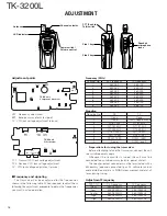
ADJUSTMENT
Adjustment points
VR1 : Frequency adjustment
BPF : Band-pass wave form test point
CV : VCO lock voltage adjustment terminal
TC1 : Transmit VCO lock voltage adjustment
TC2 : Receive VCO lock voltage adjustment
CV : VCO lock voltage adjustment terminal
■
Frequency and signaling
The transceiver has been adjusted for the frequencies
shown in the following table. When required, readjust them
following the adjustment procedure to obtain the frequencies
you want in actual operation.
VR1
BATT+
5M
5C
PCTV
BPF
CV
B
SB
CN13
ANT
TX-RX unit
Component side view
SP+
SP–
TC1
TC2
CV
TX-RX unit
Foil side view
S401
PTT
S403
SW1
S402
SW2
J301
EXT. SP/EXT. MIC
Frequency (MHz)
Channel No.
RX Frequency
TX Frequency
1
460.050
460.100
2
450.050
450.100
3
469.950
469.900
4
460.000
460.000
5
460.200
460.200
6
460.400
460.400
7
455.050
455.100
8
465.050
465.100
Antenna
LED indicator
PTT (Push to
Talk) switch
Side 1 key
Side 2 key
Speaker/
microphone
jacks
Channel selector
Power switch/
Volume control


