


TH-K40A/K40E
2
Document Copyrights
Copyright 2012 by JVC KENWOOD Corporation. All
rights reserved.
No part of this manual may be reproduced, translated,
distributed, or transmitted in any form or by any means,
electronic, mechanical, photocopying, recording, or other-
wise, for any purpose without the prior written permission of
JVC KENWOOD Corporation.
Disclaimer
While every precaution has been taken in the preparation
of this manual, JVC KENWOOD Corporation assumes no
responsibility for errors or omissions. Neither is any liability
assumed for damages resulting from the use of the informa-
tion contained herein. JVC KENWOOD Corporation reserves
the right to make changes to any products herein at any time
for improvement purposes.
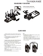
DISASSEMBLY FOR REPAIR
1. Separating the Case Assembly from the
Chassis
1. Remove the two knobs (
a
).
2. Remove the two screws (
b
).
3. Pull off the cap from SP/MIC jack (
c
).
4. Expand the right and left sides of the bottom of the case
assembly, Iift the chassis, and remove it from the case as-
sembly (
d
).
5. Taking care not to cut the speaker lead wire with connec-
tor (
e
), open the chassis and case assembly.
b
b
a
a
c
d
2. Removing the TX-RX unit from the
Chassis
1. Remove the packing (
f
).
2. Remove the 13 screws (
g
).
3. Remove the packing (
h
) and two hexagon nuts (
i
).
4. Remove the solder from the antenna terminal using a sol-
dering iron then lift the unit off (
j
).
Note:
When reassembling the unit in the chassis, be sure to sol-
der the antenna terminal.
e
Red
Black
Summary of Contents for TH-K40A
Page 34: ...TH K40A K40E 34 MEMO ...
Page 36: ...TH K40A K40E ...