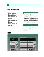


REGULATED DC POWER SUPPLIES
60
Power Switch
To enhance the safety of the power supply, the protect function
based on an AC power relay is provided separately from the power
switch. The AC power relay can be turned on/off from a external
signal while leaving the power switch in the on position.
GP-IB Adapter for expanding the PS Series to a
GP-IB System, with 12 bits 4 built-in D/As.
GP-IB Adapter for PS Series Power Supplies
Applications
●
Reliability testing of electronic parts.
●
Semiconductor aging
systems.
●
Durability testing of rotary and drive equipment.
●
Operation testing of HIC, etc.
●
Testing of board, packaging unit or
electrical parts.
●
Alternative to a battery.
●
Secondary battery
testing.
●
Production or plating of electrolytic capacitors.
●
LCD
aging systems.
Function
OVP Presetting
Pressing the OVP switch displays the OVP (Over Voltage
Protector) trip voltage on the voltmeter. This lets you perform
setting and verification without interrupting operation, even while
the output is on.
Digital Display
A bright, easy-to-read red LED shows the voltage and current
simultaneously. The voltage can be measured in 3-1/2 digits (auto-
ranging) with a maximum display resolution of 10 mV with all
models. The current can be measured in 3-1/2 digits (auto-
ranging) with a maximum display resolution of 10 mA with models
with rated cur rents below 50 A, and in 3-1/2 digits with a
maximum display resolution of 100 mA with models with rated
currents of 50 A or more (3-digit, 1 A resolution with the PS10-
210).
Output Switch
The output switch uses an electronic switch system to eliminate
chattering or noise. The switch is set automatically to off when
power is switched on so that unexpected output is not produced.
The output can be fixed to on or the output on/off switching can
be remote controlled with an external signal according to the DIP
switch selection.
Limit Switch
Pressing the LIMIT switch displays the constant voltage setting
value on the voltmeter and the constant current setting value
(current limiting value) on the ammeter. This makes setting and
verification possible without interruption, even while the output is
on.
Switch
Mode
Description
POWER SELECT
Remote/local switching of AV power
relay on/off.
OUTPUT SELECT
Remote/local switching of output
on/off.
OUTPUT SELECT
Switching for fixing output to on.
Remote/local switching of output
voltage, voltage/resistance mode
selection for remote control.
CV.CONTROL
●
Control by an external voltage
SELECT
●
Control by an external resistance
(Normal mode)
S1
●
Control by an external resistance
(Fail-safe mode)
Remote/local switching of output
current, voltage/resistance mode
selection for remote control.
CC.CONTROL
●
Control by an external voltage
SELECT
●
Control by an external resistance
(Normal mode)
[
●
Control by an external resistance
(Fail-safe mode)]
Compensation for the resistance due
REMOTE SENSING
to load lines, and the voltage drop or
stability degradation due to contact
resistance.
●
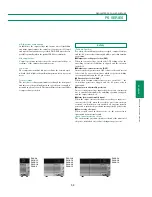
The PS Series control functions are implemented according to rear panel
control switch S1 and terminals J1 and J2. The specification inside
【
】
is possible by special order.
GP-600
【
GP-600 Specifications
】
GP-IB
Electrical specifications
: conform
s
to IEEE488.1-1978
Mechanical specifications
: conform
s
to IEEE488.1-1978
Interface function
: SH1, AH1, T6, L3, SR1, RL1,
PP0, DC1, DT1, C0
Address
: Addresses 0 to 30 can be set
using an address switch.
Listen-only mode
: Can be set with L-ONLY switch
Transmission delimiter selection
: Can be set with the EOI/CR.LF
switch
Output on/off function:
:Output can be off by manually with
the OUTPUT OFF key.
Service request function
:
GP-IB command error, GP-IB
parameter error, OVP function
and alarm functions (OCP,
OTP and POWER cut), CV
function, CC function and
OUTPUT OFF key
Analog Output
Output voltage range
: 0 to
+
10V (A, B Output/CH1
)
: 0 to
+
10V (C, D Output/CH2
)
Full scale voltage range
:
+
10V
±
15
%
(A, B Output/CH1
)
:
+
10V
±
15
%
(C, D Output/CH2
)
Maximum output current
: 3mA (A, B Output/CH1
)
: 3mA (C, D Output/CH2
)
D/A converter resolution
12bit, 0.025
%
(2.4mV) (A, B Output/CH1
)
12bit, 0.025
%
(2.4mV) (C, D Output/CH2
)
Setting accuracy
: 0.0275
%
(A, B Output/CH1
)
: 0.0275
%
(C, D Output/CH2 )
Output ripple (10Hz to 1MHz)
: 300µVrms (A, B Output/CH1
)
: 300µVrms (C, D Output/CH2
)
Supply voltage regulation (
±
10
%
fluctuate
)
: 1.5mV (A, B Output/CH1
)
: 1.5mV (C, D Output/CH2
)
Temperature coefficient
: 50ppm/
°
C (Typ) (A, B Output/CH1
)
: 50ppm/
°
C (Typ) (C, D Output/CH2
)
Rise time (10 to 90
%
, 10k
Ω
load
)
: 100µs or less (A, B Output/CH1
)
: 100µs or less (C, D Output/CH2
)
Digital I/O
Control signal
Output ON/OFF
: TTL level Low (ON)/High (OFF)
Power
・
Relay ON/OFF
: TTL level Low (ON)/High (OFF)
Status signal
CV function (SRQ)
: TTL level Low (CV)/High (no change)
CC function (SRQ)
: TTL level Low (CC)/High (no change)
Alarm ON
(
SRQ)
: TTL level Low (ON)/High
Power ON/OFF : Low
(
ON
)
OVP ON (SRQ) : Low
(
ON
)
Temperature/humidity for characteristics
in spec.
: 0
°
C to 40
°
C, 80
%
or less
Power source
: 100V
±
10
%
, 120V/220V/240V
(
250Vmax
)
AC,
(internally switchable)
Power consumption
: 10W
Case dimensions
: 70 (W)
×
124 (H)
×
351 (D)
Weight
: 2.5kg
Accessories : Instruction manual
×
1
20pin flat cable
×
2


