background image

39

R

emote Setup

Chapter Two : Setting Up the Remote Control Unit

5. See “Noting Your Devices” on page 3 to check the de-

vices and the jacks to which they are connected.

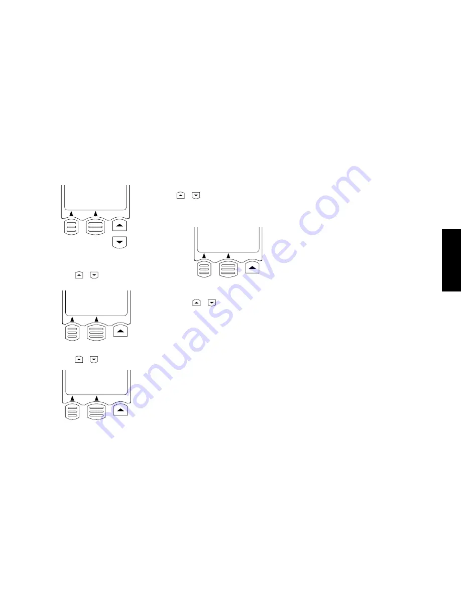
6. Select a device connection jack name (CD1, MD/Tape1,

etc.) using the 

 or 

  key, then press the Enter key

(LCD function key 2).

7. Select the device name connected to the jack (CD, Tape,

etc.) using the 

 or 

  key, then press the Enter key.

8. Select the manufacturer name of the device using the

 or 

  key, then press the Enter key.

If the manufacturer name of the device is not listed, se-
lect "Nothing" and press the Enter key. In this case, the
code can be programmed using the Learn function (see
page 40).

01.0505

02.Nothing

Back  Enter

9. Select the setup code of the device (each device has a

remote control identification number matching it) us-

ing the 

 or 

  key.

• When the device is connected through a KENWOOD

system control cord, select System. In this case, the
remote control signal is sent to the receiver then to
the device connected to it.

10. Press the 

AV.POWER

 key.

Pressing the 

AV.POWER

 key causes Remote Control unit

to transmit the signal turning on/off the device being
set. The device is turned on if the selected setup code is
correct. If it is not turned on, select another code and
press the 

AV.POWER

 key again. In case it cannot be

turned on by any code, see “If a device cannot be re-
mote controlled with any code in the list, or to add re-
mote control target functions...”.

Skip this step if 

System

 is selected in the setup code se-

lection.

11. After ensuring that the setup code is correct, press the

Enter key.

12. The display in step 3 re-appears.

Set other devices by repeating steps 4 to 11 for each of them.

To change a setup code:

When a new device is purchased to replace the previously
connected device, it is required to let Remote Control unit
identify the new device as described below.

1. Connect the new device (see pages 4 to 32).

2. Perform the procedure in “Identifying Components for

Remote Control Unit” on page 38 to select the jacks of
the new device and enter a new setup code. The newly
selected code replaced the previous code at the moment
the Enter key is pressed to save the new code.

To delete a setup code:

When a device is disconnected and no replacing device is
connected, it is required to remove the setup code from this
Remote Control unit memory as described below.

1. Perform the procedure in “Identifying Components for

Remote Control Unit” on page 38 to select the jacks
where the disconnected device was connected.

2. In step 7, select “Delete” by scrolling the device names.

This makes Remote Control unit no longer identify the
device.

• If you select “Delete”, the setup is deleted together

with the input name. For example, once you delete

VIDEO1

 to 

VIDEO3

, the 

VIDEO1

 to 

VIDEO3

 inputs

are skipped even when they are selected.

• If you select “No Type”, the input name is displayed

but only the registered device name is deleted.

01.CD1

02.MD/Tape1

03.CD-R

Back  Enter

01.CD

02.Tape

03.MD

Back  Enter

Kenwood

Akai

Alba

Back  Enter

Summary of Contents for KRF-V7773D

Page 1: ... CH K P T M X Y OC 9911 VR 4090 VR 4080 KRF V7773D This instruction manual is used to describe multiple models listed above Model availability and features functions may differ depending on the country and sales area ...

Page 2: ...igital Theater Systems Inc All rights reserved The above are additional trademarked names appearing in this manual All other products named are trademarks of their respective companies As an ENERGY STAR Partner Kenwood Corporation has deter mined that this products meets the ENERGY STAR guidelines for energy efficiency This product can save energy Saving energy reduces air pol lution and lowers ut...

Page 3: ...oltage selector switch Move switch lever to match your line voltage with a small screwdriver or other pointed tool The AC voltage selector switch on the rear panel is set to the voltage that prevails in the area to which the unit is shipped Before connecting the power cord to your AC outlet make sure that the setting position of this switch matches your line voltage If not it must be set to your v...

Page 4: ...power cord and then reset the switch plug the power cord back in and turn the power switch on CHANNEL SPACE DE EMPHASIS switch Area CHANNEL SPACE freq DE EMPHASIS USA Canada and South American Countries Other Countries 1 2 FM 100 kHz AM 10 kHz FM 50 kHz AM 9 kHz 75 µs 50 µs ND AM 50 µs FM 50kHz AM 9kHz 75 µs FM 100kHz AM 10kHz DE EMPHASIS CHANNEL SPACE RF REMOTE CONTROL UNIT RC R0910 2WAY LCD REMO...

Page 5: ...ecting Your MD Recorder or Primary Tape Deck 20 To Connect an MD Recorder To Connect a Primary Tape Deck To Connect a Secondary Tape Deck Connecting Your Secondary CD Player or Tape Deck 22 To Connect a Secondary CD Player To Connect a Secondary Tape Deck Connecting Your Laser Disc Player with AC 3 RF Output 24 To Connect an AC 3 RF Output Laser Disc Player Connecting Your Laser Disc Player withou...

Page 6: ...ol unit 38 If a device cannot be remote controlled with any code in the list or to add remote control target functions RF Remote Control Function VR 4090 VR 4080 only 42 Changing the RF Transmission Frequency Chapter Three Setting Up on the Receiver 43 Preparation for setup Speaker setup Chapter Four Warnings and Specifications 45 Warnings VR 4090 VR 4080 Specifications KRF V7773D Specifications ...

Page 7: ...reliably Be sure not to block the ventilation area on the top or back or both sides of the receiver with another device These areas should be USA and Canada at least 6 inches 15 cm from any ob struction Other countries at least top 50cm back 10cm and left and right side 10cm Do not install your receiver where direct sunlight or high frequency flourescent lighting can shine dm ë tly into the remote...

Page 8: ...DVD CD1 VIDEO2 VIDEO3 OPTICAL COAXIAL DIGITAL IN DE EMPHASIS CHANNEL SPACE The following diagram shows the entire back of the VR 4090 VR 4080 KRF V7773D AC Plugs AC voltage selector switch only for some areas Speaker wire binding post Digital jacks coaxial and optical VR 4090 Audio component jacks Pre out jacks RF Remote antenna jack only VR 4090 VR 4080 Channel space FM de emphasis switch only fo...

Page 9: ...e them For VR 4080 KRF V7773D If you will be connecting a DVD player or other compo nent with a digital output please refer to the following chart before choosing a video jack set You will need this information later when you set up your remote control unit see Identifying Components For Re mote Control Unit on page 38 Recording this informa tion now will save you additional trips behind your home...

Page 10: ...DEO2 VIDEO1 DVD FRONT R L AUDIO SIGNAL GND R L L R L R AUDIO PRE OUT RFREMOTEANTENNA SYSTEM CONTROL PHONO CD1 REC OUT PLAY IN MD TAPE1 REC OUT PLAY IN CD R CENTER FRONT SURROUND SUB WOOFER REC OUT PLAY IN CD2 TAPE2 MONITOR SL 16 TEXT REMOTE IROUTLCD IRRECEIVERIN SURROUND SPEAKERS CENTERSPEAKER DC12V 20mA IR REPEATER OUT R L FRONT SPEAKERS B L R A R L C AC 120V 60Hz SWITCHED TOTAL 90W 0 75A MAX ANT...

Page 11: ...en the posts they will not conduct sound properly to the speakers 2 Follow the steps under To Connect Front Speakers Only on this page to connect the RIGHT and LEFT FRONT speakers 3 Insert the plug from the positive jack on the CENTER speaker into the pin jack on the positive CENTER post Repeat for the negative plug 4 Insert the plug from the positive jack on the RIGHT SURROUND speaker into the pi...

Page 12: ... GND R L L R L R AUDIO PRE OUT RFREMOTEANTENNA SYSTEM CONTROL PHONO CD1 REC OUT PLAY IN MD TAPE1 REC OUT PLAY IN CD R CENTER FRONT SURROUND SUB WOOFER REC OUT PLAY IN CD2 TAPE2 MONITOR SL 16 TEXT REMOTE IROUTLCD IRRECEIVERIN SURROUND SPEAKERS CENTERSPEAKER DC12V 20mA IR REPEATER OUT R L FRONT SPEAKERS B L R A R L C AC 120V 60Hz SWITCHED TOTAL 90W 0 75A MAX ANTENNA GND AM AC 110 120V AC 220 240V Po...

Page 13: ... s built in amplifiers Do not plug in the amplifiers or the receiver to AC power until all connections have been made To connect supplemental power amplifiers 1 Using RCA audio cables not supplied connect the receiver s PRE OUT jacks to the amplifiers input jacks as shown to the left 2 Connect the speakers to the power amplifiers according to the amplifiers instruction manuals ...

Page 14: ...OUT PLAY IN PLAY IN PLAY IN PLAY IN MONITOR OUT SURROUND CENTER SUBWOOFER DVD 6 CH INPUT VIDEO4 VIDEO3 VIDEO2 VIDEO1 DVD FRONT R L AUDIO SIGNAL GND R L L R L R AUDIO PRE OUT RFREMOTEANTENNA SYSTEM CONTROL PHONO CD1 REC OUT PLAY IN MD TAPE1 REC OUT PLAY IN CD R CENTER FRONT SURROUND SUB WOOFER REC OUT PLAY IN CD2 TAPE2 MONITOR SL 16 TEXT R IR SU R ANTENNA GND AM COMPOSITE VIDEO S VIDEO ...

Page 15: ...ation under Before You Begin on page 1 It contains important notes about the types of video connections you can make 2 Connect a video cable from your TV s Video IN jack to the receiver s MONITOR OUT jack as shown to the left 3 If your TV does not have any video input connections you must purchase an RF modulator The modulator will convert the video signal from the receiver to an RF sig nal that w...

Page 16: ... FRONT SURROUND SUB WOOFER REC OUT PLAY IN CD2 TAPE2 MONITOR SL 16 TEXT REMOTE IROUTLCD IRRECEIVERIN SURROUND SPEAKERS CE DC12V 20mA IR REPEATER OUT R L FRONT SPEA B L R C ANTENNA GND AM PLAY IN VIDEO1 REC OUT PLAY IN VIDEO2 PLAY IN VIDEO3 PLAY IN VIDEO4 AUDIO OUTPUT VIDEO OUT S VIDEO OUT DIGITAL OUT COAXIAL OR OPTICAL Remove protective cap before connecting Note that video device jacks are linked...

Page 17: ...tuner s Audio Out jacks to the receiver s VIDEO2 VIDEO3 or VIDEO4 VR 4090 only PLAY IN jacks as shown to the left 3 Leave the cable tuner s video out RF jack connected directly to your VCR or TV wherever you already have it connected See How Do I Operate Devices on page 28 of the Users Guide for details about using this setup 4 Go to Noting Your Devices on page 3 and note which jack you used to co...

Page 18: ...PLAY IN PLAY IN PLAY IN MONITOR OUT SURROUND CENTER SUBWOOFER DVD 6 CH INPUT VIDEO4 VIDEO3 VIDEO2 VIDEO1 DVD FRONT R L AUDIO SIGNAL GND R L L R L R AUDIO PRE OUT RFREMOTEANTENNA SYSTEM CONTROL PHONO CD1 REC OUT PLAY IN MD TAPE1 REC OUT PLAY IN CD R CENTER FRONT SURROUND SUB WOOFER REC OUT PLAY IN CD2 TAPE2 MONITOR SL 16 TEXT ANTENNA GND AM AUDIO OUT VIDEO IN S VIDEO OUT S VIDEO IN AUDIO IN VIDEO O...

Page 19: ...and video cables from the VCR s Audio and Video jacks to the receiver s VIDEO1 REC OUT and PLAY IN jacks as shown to the left 3 Be sure to connect the VCR Video IN cable to the jack labeled REC OUT and the VIDEO OUT cable to the jack labeled PLAY IN 4 Go to Noting Your Devices on page 3 and note which jack you used to connect your VCR In addition note the brand name and model number of the VCR To ...

Page 20: ...EO1 DVD FRONT R L AUDIO SIGNAL GND R L L R L R AUDIO PRE OUT RFREMOTEANTENNA SYSTEM CONTROL PHONO CD1 REC OUT PLAY IN MD TAPE1 REC OUT PLAY IN CD R CENTER FRONT SURROUND SUB WOOFER REC OUT PLAY IN CD2 TAPE2 MONITOR SL 16 TEXT REMOTE IROUTLCD IRRECEIVERIN SURROUND SPEAKERS CENTERSPEAKER DC12V 20mA IR REPEATER OUT R L FRONT SPEAKERS B L R A R C ANTENNA GND AM OUTPUT COMMUNICATION CABLE KENWOOD ONLY ...

Page 21: ...e Several Kenwood Devices System Control Chaining on page 32 for more information 4 Connect the SL16 text cable communication cable from the changer to the receiver s SL16 TEXT jack as shown to the left 5 Go to Noting Your Devices on page 3 and note which jacks you used to connect your CD changer In addi tion note the brand name and model number of the CD Changer When playing a HDCD disc in the HD...

Page 22: ...URROUND CENTER SUBWOOFER DVD 6 CH INPUT VIDEO4 VIDEO3 VIDEO2 VIDEO1 DVD FRONT R L AUDIO SIGNAL GND R L L R L R AUDIO PRE OUT RFREMOTEANTENNA SYSTEM CONTROL PHONO CD1 REC OUT PLAY IN MD TAPE1 REC OUT PLAY IN CD R CENTER FRONT SURROUND SUB WOOFER REC OUT PLAY IN CD2 TAPE2 MONITOR SL 16 TEXT ANTENNA GND AM Remove protective cap before connecting SUBWOOFER OUT CENTER OUT SURROUND OUT FRONT OUT VIDEO O...

Page 23: ...ical from the DVD s digital jack to the appropriate digital jack on the receiver as shown to the left The illustration shows two digital connections one for coaxial connection and one for optical connection Your DVD player supports one or the other of these connec tion methods do not connect both If you use the optical digital cable be sure to remove the protective cover from the optical jack befo...

Page 24: ...ER DVD 6 CH INPUT VIDEO4 VIDEO3 VIDEO2 VIDEO1 DVD FRONT R L AUDIO SIGNAL GND R L L R L R AUDIO PRE OUT RFREMOTEANTENNA SYSTEM CONTROL PHONO CD1 REC OUT PLAY IN MD TAPE1 REC OUT PLAY IN CD R CENTER FRONT SURROUND SUB WOOFER REC OUT PLAY IN CD2 TAPE2 MONITOR SL 16 TEXT FM 75 ANTENNA GND AM Remove protective cap before connecting DIGITAL RECORD IN COAXIAL OR OPTICAL RECORD IN ANALOG PLAY OUT ANALOG D...

Page 25: ...eiver s CD R PLAY IN jacks as shown to the left 2 Connect the audio cable from the CD R recorder s Rec IN jacks to the receiver s CD R REC OUT jacks as shown to the left 3 VR 4090 only When the CD R recorder has digital jacks connect digital coaxial or optical cables between the CD R recorder s digital jacks and the receiver s CD R digital jacks as shown to the left Although the fig ure shows both...

Page 26: ... CENTER SUBWOOFER DVD 6 CH INPUT VIDEO4 VIDEO3 VIDEO2 VIDEO1 DVD FRONT R L AUDIO SIGNAL GND R L L R L R AUDIO PRE OUT RFREMOTEANTENNA SYSTEM CONTROL PHONO CD1 REC OUT PLAY IN MD TAPE1 REC OUT PLAY IN CD R CENTER FRONT SURROUND SUB WOOFER REC OUT PLAY IN CD2 TAPE2 MONITOR SL 16 TEXT S ANTENNA GND AM Remove protective cap before connecting RECORD IN ANALOG PLAY OUT ANALOG DIGITAL RECORD IN COAXIAL O...

Page 27: ...m the optical jacks You only need to connect to the digital out jack if you will be recording from sources that are connected to a digital in jack such as a CD or DVD player 4 If you are connecting a Kenwood MD recorder connect the system control cable from the MD recorder to the receiver If you are connecting more than one Kenwood device with a system control cable see What if I Have Several Kenw...

Page 28: ...LAY IN REC OUT PLAY IN PLAY IN PLAY IN PLAY IN MONITOR OUT SURROUND CENTER SUBWOOFER DVD 6 CH INPUT VIDEO4 VIDEO3 VIDEO2 VIDEO1 DVD FRONT R L AUDIO SIGNAL GND R L L R L R AUDIO PRE OUT RFREMOTEANTENNA SYSTEM CONTROL PHONO CD1 REC OUT PLAY IN MD TAPE1 REC OUT PLAY IN CD R CENTER FRONT SURROUND SUB WOOFER REC OUT PLAY IN CD2 TAPE2 MONITOR SL 16 TEXT ANTENNA GND AM CD OUTPUT OR TAPE PLAY OUT TAPE REC...

Page 29: ...e CD player s audio jacks to the receiver s CD2 TAPE2 MONITOR PLAY IN jack set as shown to the left Do not connect the system control cable from the sec ond CD player even if it supports system control 2 Go to Noting Your Devices on page 3 and note which jacks you used to connect your CD player In addition note the brand name and model number of the CD player If you connect a second tape deck you ...

Page 30: ...OOFER DVD 6 CH INPUT VIDEO4 VIDEO3 VIDEO2 VIDEO1 DVD FRONT R L AUDIO SIGNAL GND R L L R L R AUDIO PRE OUT RFREMOTEANTENNA SYSTEM CONTROL PHONO CD1 REC OUT PLAY IN MD TAPE1 REC OUT PLAY IN CD R CENTER FRONT SURROUND SUB WOOFER REC OUT PLAY IN CD2 TAPE2 MONITOR SL 16 TEXT ANTENNA GND AM RF DEMODULATOR COAX OPT DIGITALOUTPUT COAX RF INPUT AC 3 RF DIGITALINPUT DC IN AUDIO OUT VIDEO OUT S VIDEO OUT AC ...

Page 31: ...s of video connections you can make 2 Connect the audio cables from the laser disc player s Audio OUT jacks to the receiver s AUDIO jacks VIDEO 3 PLAY IN as shown to the left Do not connect the digital cable coaxial or optical yet it must be connected via the demodulator as described in the following steps 3 Connect the AC 3 RF coaxial cable from the laser disc player s AC 3 RF OUT jack to the dem...

Page 32: ...AL GND R L L R L R AUDIO PRE OUT RFREMOTEANTENNA SYSTEM CONTROL PHONO CD1 REC OUT PLAY IN MD TAPE1 REC OUT PLAY IN CD R CENTER FRONT SURROUND SUB WOOFER REC OUT PLAY IN CD2 TAPE2 MONITOR SL 16 TEXT ANTENNA GND AM AUDIO OUT VIDEO OUT S VIDEO OUT Remove protective cap before inserting DIGITAL OUT COAXIAL OR OPTICAL Note that video device jacks are linked to specific digital jacks For example if you ...

Page 33: ...he types of video connections you can make 2 Connect the audio cables from the laser disc player s Audio OUT jacks to the receiver s AUDIO jacks as shown to the left 3 Connect the video cable from the laser disc player s Video OUT jack to the receiver s VIDEO PLAY IN jack as shown to the left Note that the jack sets are linked even though they are not adjacent You must connect all of the cables fr...

Page 34: ... TEXT ANTE AUDIO OUT GROUND Do not plug in the receiver to AC power until you have connected all your devices This section focuses on the connections from your turntable record player to the VR 4090 VR 4080 KRF V7773D Please refer to your turntable record player s instructions for more detail about its connection jacks and capabilities To Connect a Turntable Record Player 1 Connect the audio cable...

Page 35: ... probably temporarily to the front of the receiver If you want a less cluttered and more permanent connection see Can I Connect an Additional VCR Perma nently below To Connect a Camcorder or Additional VCR Connect the audio and video cables from the camcorder or VCR s Audio and Video jacks to the receiver s front panel jacks as shown to the left Can I Connect an Additional VCR Permanently Yes To d...

Page 36: ...3 VIDEO2 VIDEO1 DVD FRONT R L AUDIO SIGNAL GND R L L R L R AUDIO PRE OUT RFREMOTEANTENNA SYSTEM CONTROL PHONO CD1 REC OUT PLAY IN MD TAPE1 REC OUT PLAY IN CD R CENTER FRONT SURROUND SUB WOOFER REC OUT PLAY IN CD2 TAPE2 MONITOR SL 16 TEXT REMOTE IROUTLCD IRRECEIVERIN SURROUND SPEAKERS CENTERSPEAKER DC12V 20mA IR REPEATER OUT R L FRONT SPEAKERS B L R A R L C AC 120V 60Hz SWITCHD TOTAL 90W 0 75A MAX ...

Page 37: ...the receiver for more than 2 seconds VR 4090 VR 4080 You will see RF OFF on the re ceiver display KRF V7773D for U S Military You will see DATA REAR IN on the receiver display To Connect any other IR Receiver 1 Connect the IR receiver s output cable to the receiver s IR RECEIVER IN jack This jack supports a 12V 20mA signal 2 Connect an AC adapter to the IR receiver Do not plug the adapter into the...

Page 38: ...witch the receiver s input automatically to a connected device when you start playback from that device synchronize recording a CD automatically when you start playback from the connected CD player SYSTEM CONTROL SYSTEM CONTROL SYSTEM CONTROL SYSTEM CONTROL Receiver CD Player MD Recorder or Tape Deck SYSTEM CONTROL cord Make sure the units are connected to the correct jacks on the receiver for exa...

Page 39: ...me you may need to exert quite a bit of pressure 2 Adjust the antenna as necessary to improve reception 3 Tack the looped end of the antenna in the location that provides the best reception FM Outdoor Antenna FM 75Ω ANTENNA GND AM Kenwood recommends a permanently installed outdoor FM antenna for best FM reception To connect an outdoor FM antenna 1 Connect the antenna wire to a standard commerciall...

Page 40: ...e figure to remove it 2 Insert four AA R6 batteries with the correct polarity Then close the battery cover Installing the Batteries This chapter is composed of the following sections Installing the Batteries Page 34 Basic Operation of Remote Control Unit Page 35 Setting Up Speakers Page 36 Identifying Components for Remote Control Unit Page 38 If Remote Control unit is used outside the remote cont...

Page 41: ... VOL key repeatedly until the desired volume is obtained Muting audio temporarily Press the MUTE key To resume the original volume press the MUTE key again or press one of the VOL keys Using the numeric keys When entering a figure directly for selecting a CD track num ber etc press the numeric keys as shown below To enter 5 To enter 25 or 2 VOL VOL Screen menu control operation 2WAY LCD REMOTE CON...

Page 42: ...n the front left and right speaker setting menu Front appears select Front Normal or Large in the same way as step 4 then press the Next key If you set the subwoofer to Off in step 4 skip this step 6 When the center speaker setting menu Center appears select Center Normal Large or Off in the same way as step 4 then press the Next key Select Off when no cen ter speaker is connected If you select No...

Page 43: ...o Normal the Center and Surround speakers can be set exclusively to Normal or Off When the Subwoofer is set to Off the Front speakers are set automatically to Large It is not possible to select Normal Surround SetUp Test Tone L 10dB Home Next 5 Test noise is generated from the front left speaker Lis ten to the volume of the noise carefully The test noise moves from a speaker to the next speaker ev...

Page 44: ...e Con trol unit capable of identifying the devices it controls Re mote Control unit provided with the receiver can be used in setup of any device Even when a device is not listed in the device codes in the Remote Control unit memory the remote control function of the device can be programmed using the Learn function The Learn function can also be used to extend the remote controllable functions Fo...

Page 45: ...te control target functions Skip this step if System is selected in the setup code se lection 11 After ensuring that the setup code is correct press the Enter key 12 The display in step 3 re appears Set other devices by repeating steps 4 to 11 for each of them To change a setup code When a new device is purchased to replace the previously connected device it is required to let Remote Control unit ...

Page 46: ...US DIMMER SUB W MUTE ENTER AUTO MONO REPEAT REC MODE RANDOM BACK LIGHT INPUT SEL TV SELECT DISPLAY SELECT AUDIO THEME FAVORITE INFO EXIT LAST CHANNEL CH CH VOL VOL RETURN PAGE OSD PAGE 2 Press the LEARN key 3 Select one of Extend1 to Extend5 using the or key then press the Enter key LCD function key 2 Press the Exit key LCD function key 2 to exit from the operation Press the Clr clear key if you w...

Page 47: ...trol signal Complete is displayed when the remote control signal has been programmed in this Remote Control unit Waiting Clr Exit Video1 DVD Menu Press the Exit key LCD function key 2 to exit from the operation 5 To program other remote control signals repeat steps 1 to 4 for each To reset a key to the factory shipment condition by clearing the previously programmed signal Press the Clr key in ste...

Page 48: ...nce of the RF remote signal is about 30 feet 10 meters provided there is no obstacle Here is list of adjustments of that can maximize the opera tion of your Remote Control unit For optimal operation of the Remote Control unit 1 Aim the Remote Control unit toward the room where the Receiver is located 2 Do not position the Receiver and the Remote Control unit near metal such as heat ducts Metal can...

Page 49: ...FF when not Selecting the FRONT speakers 3 Press the SET UP key to display FRONT LARGE or NORMAL 4 Press the MULTI CONTROL fi key to select FRONT LARGE large sized speakers or NOR MAL normal sized speakers If the SUBWOOFER is set to OFF the FRONT speakers are set automatically to LARGE and the CENTER speaker selection display appears automati cally Selecting the CENTER speaker 5 Press the SET UP k...

Page 50: ...ULTI CONTROL fi key 6 Similarly adjust the volumes from the R front right RS right surround and LS left surround speakers 7 Press the SET UP key to proceed to Selecting the speaker distances below To exit from setting press the SET UP key repeatedly until SETUP FIXED is displayed Do not adjust the SW Sub Woofer volume using the test noise It should be adjusted while listening to ordinary music 3 S...

Page 51: ...sures Reorient or relocate the receiving antenna Increase the separation between the equipment and the receiver Connect the equipment into an outlet on a circuit dif ferent from the one that the receiver is connected to Consult the dealer or an experienced radio TV techni cian for help FCC Compliance Notice Audio video Receiver VR 4090 and VR 4080 and Remote Controller RC R0911 These devices compl...

Page 52: ...46 Specifications Chapter Four Warnings and Specifications ...

Page 53: ...0 5Vp p 75Ω Onput Level Impedance Wavelength Optical 15dBm 21dBm 660nm 30nm Video Section Video Inputs Outputs Video composite 1Vp p 75Ω S Video luminance signal 1Vp p 75Ω chrominance signal 0 286Vp p 75Ω FM Tuner Section Tuning Frequency Range 87 5MHz 108MHz Usable Sensitivity Mono 1 2µV DIN at 75Ω 13 2dBf 40kHz dev S N 26dB Usable Sensitivity STEREO 45µV DIN at 75Ω 44 2dBf 46kHz dev S N 46dB Tot...

Page 54: ...er 15 D deleting component with Setup code 39 digital cable CD player 14 CD R recorder 18 DVD player 16 laser disc player AC 3 Output 24 laser disc player no AC 3 Output 26 MD recorder 20 Dolby Digital AC 3 RF Out 24 DVD player connecting 16 identifying for Remote Control unit 38 E external infrared receiver connecting 30 F FM antenna connecting 33 front speakers connecting 4 G ground cable connec...

Page 55: ...corder 21 setup codes for components 39 tape deck 21 system control chaining 32 T tape deck connecting 20 identifying for Remote Control unit 38 turntable record player connecting 28 TV connecting 8 identifying for Remote Control unit 38 watching without using receiver 9 V VCR connecting 12 identifying for Remote Control unit 38 video cables another VCR 29 camcorder 29 DVD player 16 laser disc pla...

Page 56: ...umber found on the back of the unit in the spaces designated on the warranty card and the space provided below Refer to the model and serial numbers whenever you call upon your dealer for information or service on this product Model Serial Number ...

Reviews: