background image

8

Preparations

KRF-V7020/V6020/V5020 (En/T)

REC OUT

PHONO

CD

MD / TAPE

VIDEO 2 / MONITOR

PLAY IN

REC OUT

PLAY IN

L

R

1

¡

4

7

6

¢

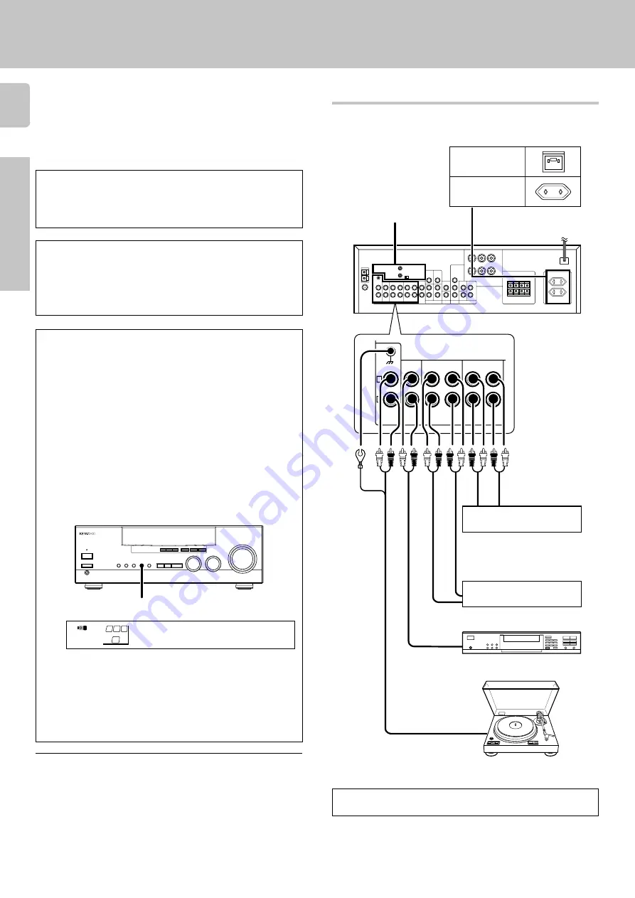
Make connections as shown below.
When connecting the related system components, be sure
to also refer to the instruction manuals supplied with the
components you are connecting.
Do not connect the power cord to a wall outlet until all
connections are completed.

Microcomputer malfunction

If operation is not possible or an erroneous display appears, even
though all connections have been made properly, reset the micro-
computer referring to “In case of difficulty”.

Notes
1. Be sure to insert all connection cords securely. If their connections are

imperfect, the sound may not  be produced or noise may interfere.

2. Be sure to remove the power cord from the AC outlet before plugging or

unplugging any connection cords. Plugging / unplugging connection
cords without disconnecting the power cord can cause malfunctions and
may damage the unit.

3. Do not connect power cords from components whose power consump-

tion is larger than what is indicated on the AC outlet at the rear of this unit.

Connecting audio components

Caution regarding placement

To AC wall outlet

Cassette deck or
MD recorder

CD player

IN

OUT

Record player

SYSTEM CONTROL
jacks

0

Shape of AC outlets

For U.K.

For other countries

Cassette deck or
graphic equalizer

^

Setting up the system

To maintain proper ventilation, be sure to leave a space around the
unit (from the largest outer dimensions, including projections) equal
to, or greater than shown below:

Left and right panels: 10 cm, Rear panel: 10 cm, Top panel: 50 cm

IN

OUT

OUT

OUT

VIDEO 2/MONITOR jacks

The receiver’s 

VIDEO 2/MONITOR

 jacks can be used in two different

ways. Make the appropriate setting for the component connected to
the jack when the receiver is turned on.

Use as a VIDEO 2 jack

You can connect a video deck or the like to these jacks and perform
video playback and recording. The initial factory setting is “

VIDEO

2”

.

Use as a MONITOR jack

You can connect a cassette deck or the like to these jacks and make
use of the deck’s monitoring function during recording. Alternately,
you can connect a graphic equalizer to these jacks to apply compen-
sation to the music signal.
To use the 

VIDEO 2/MONITOR

 jacks as 

MONITOR

 jacks, hold down

the 

VIDEO 2/MONITOR

 key of the main unit for more two seconds so

that the indication shown below appears.

• At the same time the setting is switched to “MONITOR,” the audio input

source switches to tuner and the video input source switches to VIDEO
1.

• To switch the setting back to “VIDEO 2,” once again hold down the

VIDEO 2/MONITOR

 key for two seconds or more.

• If you decide to use the VIDEO 2/MONITOR jacks as 

MONITOR

 jacks,

make sure to delete the “

VIDEO 2 

(VCR2)” input from the preset

remote control (RC-R0508).

RC

6

 VIDEO 2/MONITOR

MONIT R

O

FM 

AM

kHz

MHz

  STEREO

DSP 

S.DIRECT

A

SP

MUTE

MUTE

DOWNMIX

PRO LOGIC

TUNED

MEMO.

AUTO

ST.

AUTO SOUND

SW

R

L

DIGITAL

B

MONITOR

To use these jacks as MONITOR
jacks, you must change the
appropriate setting.

To use the receiver for video recording, connect a video deck to
the VIDEO 2/MONITOR jacks.

Summary of Contents for KRF-V5020

Page 1: ...e control to control other audio video components In order to effectively use the remote control it is important to read the operating instructions and obtain a proper understanding of the remote control and how to switch its operation modes etc Using the remote control without completely understanding its design and how to switch the operation modes may result in incorrect operations This instruc...

Page 2: ... product When they empty you should not throw away Instead hand them in as small chemical waste THE EXCLAMATION POINT WITHIN AN EQUILATERAL TRI ANGLE IS INTENDED TO ALERT THE USER TO THE PRES ENCE OF IMPORTANT OPERATING AND MAINTENANCE SERVICING INSTRUCTIONS IN THE LITERATURE AC COMPANYING THE APPLIANCE Cleaning Do not use volatile solvents such as alcohol paint thinner gasoline or benzine etc to ...

Page 3: ...3 Speaker settings 13 Normal playback 14 Preparing for playback 14 Listening to a source component 15 Adjusting the sound 15 Recording 16 Recording audio 16 Recording video 16 Listening to radio broadcasts 17 Tuning non RDS radio stations 17 Using RDS Radio Data System 17 Using the DISPLAY key 18 Presetting RDS stations RDS AUTO MEMORY 18 Presetting radio stations manually 19 Receiving preset stat...

Page 4: ...w you the name of the current broadcast station and PTY search to let you tune stations by program type PTY Program TYpe search Lets you tune stations by specifying the type of program you want to hear EON Enhanced Other Networks reservation The EON function lets you monitor information on other stations so you can receive traffic or news programs as soon as they are broadcast even they are broadc...

Page 5: ...ob 0 PHONES jack Use for headphone listening SPEAKERS A key Use to turn speaker system A on and off SPEAKERS key KRF V5020 Use to turn the speakers on and off SPEAKERS B key Use to turn speaker system B on and off MUTE key KRF V5020 Use to temporarily mute the sound About the STANDBY indicator This unit has a STANDBY indicator When the STANDBY indicator is lit the unit consumes a small amount of p...

Page 6: ...to select the listening mode SETUP key Use to select the surround sound settings 1 POWER key Use to turn the receiver on and off Use in combination with the input selector AUDIO VIDEO or TV keys and SHIFT key to turn various components on and off 2 MACRO key RC5 Use in combination with the AUDIO VIDEO or TV keys to execute a series of com mands automatically MACRO PLAY 3 VIDEO selector key Selects...

Page 7: ... the input source this A and B of a double cassette deck 7 DVD CONT keys Used to operate DVD player While holding this key depressed press any of the keys masked in gray in the above illustration to operate the corre sponding function of a DVD player from KENWOOD Keys 3 4 5 9 and are given the following functions during the DVD player control operation 3 TITLE 4 ENTER 5 SUB TITLE 9 MENU OSD For de...

Page 8: ...argest outer dimensions including projections equal to or greater than shown below Left and right panels 10 cm Rear panel 10 cm Top panel 50 cm IN OUT OUT OUT VIDEO 2 MONITOR jacks The receiver s VIDEO 2 MONITOR jacks can be used in two different ways Make the appropriate setting for the component connected to the jack when the receiver is turned on Use as a VIDEO 2 jack You can connect a video de...

Page 9: ... for use indoors Place it as far as possible from the receiver TV set speaker cords and power cord and adjust the direction for best reception FMindoorantenna The supplied indoor antenna is for temporary use only For stable signal reception we recommend using an outdoor antenna Disconnect the indoor antenna when you connect one outdoors FMoutdoorantenna Lead the 75Ω coaxial cable connected to the ...

Page 10: ... MD or analog discs SWITCHING FROM SL16 TO XS8 This operation will not effect items stored in the memory After switching the system control mode turn the power off and unplug the power cord from the wall outlet then plug it back You can easily change the system control mode by adjusting the position of the SYSTEM CONTROL switch on the rear panel Do this operation after completing all connections O...

Page 11: ...d on the rear panel of the receiver connect speakers with matching imped ance ratings Using speakers with a rated impedance other than that indicated on the rear panel of the receiver could result in malfunctions or damage to the speakers or receiver Setting up the system PRE OUT connections This receiver has additional preout jacks These can be used for various purposes but will need to be connec...

Page 12: ...ailable Setting up the system Loading the batteries Preparingtheremotecontrol RC R0508 Insert four AAA size LR03 batteries as indicated by the polarity markings 3 Close the cover 2 Insert the batteries 1 Remove the cover Notes 1 The supplied batteries may have shorter lives than ordinary batteries due to use during operation checks 2 Replace all four batteries with new ones when you notice a short...

Page 13: ... speaker volume level adjustment mode In steps 3 and 4 indications appear only for the selected channels of the speakers that require adjusting To enable you to obtain optimum enjoyment from the receiver s listening modes make sure to complete the speaker settings as described below sUBW Es Y A SP SW R L STEREO CNTR ML N A SP SW R L STEREO Loading the batteries Preparingtheremotecontrol RC R0710 I...

Page 14: ...t Indication in meters Display when all speakers have been selected Lch dB 1 A SP SW L 1 FT M 3 A SP R L CD SW R L Preparing for surround sound Preparingforplayback Normal playback Some preparatory steps are needed before starting playback Turningonthereceiver 1 Turn on the power to the related components 2 Turn on the power to this receiver by pressing POWER and ON STANDBY keys SelectingTAPE MD S...

Page 15: ... this point to turn off the remote control s own adjustment mode In this case the input source is not switched The input sources change as shown below Selecting a source using the INPUT SELECTOR knob Use the input selector INPUT SELECTOR AUDIO VIDEO to select the source you want to listen to Selecting a source using the AUDIO key on the remote control RC R0508 Selecting a source using the VIDEO ke...

Page 16: ...e deck con nected to the MD TAPE jacks Copying tapes 1 Use the input selector to select TAPE 2 Start playback on the cassette deck connected to the MD TAPE jacks and start recording on the cassette deck connected to the VIDEO2 MONITOR jacks MONITOR TAPE copying TAPE MONITOR copying To copy tapes using a double cassette deck refer to the instruc tion manual of the double cassette deck MONITORfuncti...

Page 17: ...l data for FM broadcasts along with the broadcast signal Tuners and receivers designed for RDS reception can extract the information from the broadcast signal for use with various functions such as automatic display of the station name RDS functions PTY Program Type Identification Search Automatically tunes to a station that is currently broadcasting the specified program type genre EON Enhanced O...

Page 18: ... AUTO ST AUTO SOUND SW R L DIGITAL B TI VOL RDS EON PTY TP TA NEWS 1 2 3 This function automatically stores up to 30 RDS stations in the preset memory In order to use the EON and PTY functions the RDS stations must be stored in the preset memory using the RDS AUTO MEMORY function Use the input selector to select the tuner Use the BAND key to set the broadcast band to FM Press and hold the MEMORY k...

Page 19: ...on assigns preset numbers to RDS stations starting from preset number 1 Therefore be sure to execute the RDS auto memory function before using the following operations to manually store AM stations and other FM stations and RDS stations Presetting RDS stations RDS AUTO MEMORY MEMORY MULTI CONTROL 01 8 9 FM MHz STEREO A SP TUNED MEMO AUTO ST SW R L When storing radio stations manually it may take a...

Page 20: ...n after several seconds the display returns to the original display Repeat steps 1 2 and 3 MULTI CONTROL PTY MULTI CONTROL PTY Press the PTY key to activate the PTY search mode While the PTY indicator is lit use the MULTI CONTROL to select the program type of your choice NEWs FM AM kHz MHz STEREO DSP S DIRECT A SP MUTE MUTE DOWNMIX MONITOR PRO LOGIC TUNED MEMO AUTO ST AUTO SOUND SW R L DIGITAL BTI...

Page 21: ...isplayed for the station being received the traffic information of this station can be received without EON reservation When waiting for information while listening to a RDS station without the EON function If the EON indicator does not light in steps 3 and 4 and the desired kind of information has already been selected the information from only the station being received will be waited for The re...

Page 22: ...not Dolby Surround encoded Dialog positioning and sound image definition however may not be as accurate when used with programs that are not Dolby Surround encoded What s DSP DSP stands for Digital Signal Processor The way a sound is heard in an actual environment depends on a variety of different factors One of the most important is reverberation the act of decaying elements of sound echoing in v...

Page 23: ...put channels and the receiver you can enjoy surround sound playback When you try to play a disc other than Dolby Digital AC 3 such as DTS CD no sound is produced or noise may be heard To avoid this situation make sure that you connect the component to the receiver s DVD 6CH INPUT jacks through a surround processor which can decode the surround signal you wont to listen to Connecting a DVD player w...

Page 24: ...ur room to watch movies or listen to music SUBWOOFERadjustment RC R0508only It is easy to adjust the volume of the subwoofer using the remote control RC R0508 1 Press the SUBWOOFER key so that SW is displayed 2 Use the VOLUME key to adjust the volume Each time you hold down the DISPLAY key for more than two seconds the display brightness changes among the three avail able settings Select the brigh...

Page 25: ... Connect it properly referring to Connecting the speakers Select a surround mode Adjust the speaker levels using the test tone Insert the audio cord plugs securely into the PHONO jacks Connect the grounding wire to the GND termi nal on the rear panel Tuner Cause No antenna is connected The broadcast band is not set properly The frequency of the desired station is not tuned Noise due to ignition no...

Page 26: ...he receiver and the remote The audio cords and system control cords are not connected properly No software is loaded in the source compo nent An attempt is made to play a tape which is being recorded in the cassette deck Remedy Replace with new batteries Operate the remote control unit within the controllable range Connect properly referring to Setting up the system 8 Place software in the source ...

Page 27: ...nal to noise ratio PHONO MM 75 dB IHF 66 CD 93 dB IHF 66 Input sensitivity impedance PHONO MM 2 5 mV 27 kΩ CD 200 mV 47 kΩ DVD 6CH SUBWOOFER 200 mV 10 kΩ Output level impedance TAPE REC 200 mV 2 2 kΩ PRE OUT CENTER SURROUND 1 V 2 2 kΩ PRE OUT SUBWOOFER 2 V 2 2 kΩ Tone control BASS 10 dB at 100 Hz TREBLE 10 dB at 10 kHz VIDEO section VIDEO inputs outputs VIDEO composite 1 Vp p 75 Ω FMtunersection T...

Page 28: ...the unit in the spaces designated on the warranty card and in the space provided below Refer to the model and serial numbers whenever you call upon your dealer for information or service on this product Model __________________ Serial Number _______________________ ...

Reviews: