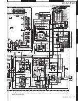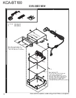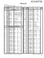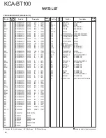
KCA-BT100
4
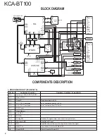
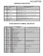
Pin No.
Pin Name
I/O
Application
Processing / Operation / Description
60
RESET
I
Reset input
L: Reset
61
REQH0
I
Communication request input from head unit
L: Communication request is found
62
BUDET
I
Detection input of momentary power down
H: Detection of momentary power down
63
PO2
-
GND
64
REQC2
I
Communication request input from CH2
L: Communication request is found
65
REQC1
I
Communication request input from CH1
L: Communication request is found
66
CHCON1
I
Changer control input from head unit
L: Changer control request
67
VSS0
-
GND
68
VDD1
-
Power supply voltage
69
X2
-
Resonator connection
70
X1
I
Resonator connection
71
IC
-
Internal connection
72
NC
-
Not used
73
CHCON2
I
CH2 control input from head unit
L: CH2 control request
74
AVDD0
-
A/D anolog power supply voltage
75
AVREF0
-
A/D reference voltage input
76~80
NC
-
Not used
●
MAIN
µ
-COM: IC3 on X32- (PROCESSOR UNIT)
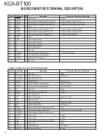
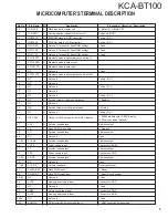
Pin No.
Pin Name
I/O
Application
Processing / Operation / Description
1,2
NC
-
Not used
L fixed
3
LX DATA S
O
Data to master unit
Pull-up (B.U.)
4
LX DATA M
I
Data from master unit
5
LX CLK
I
LX-BUS clock
Pull-up (B.U.)
6
BYTE
-
External data bus switching input
Connects to GND
7
CNVSS
-
Processor mode switching input
Pull-down (GND)
8,9
NC
-
Not used
L fixed
10
RESET
I
Forced reset from master unit
L: Reset
11
XOUT
O
Main clock output
12
VSS
-
Power supply input
Connects to GND
13
XIN
I
Main clock input
14
VCC1
-
Power supply input
Connects to B.U.5V
15
NMI
I
NMI interruption input
Pull-up (B.U.)
16
PON2
O
Circumference power supply control (5V)
L: ON
17
LX CON
I
Start-up request from master unit
H: Slave unit ON, L: Slave unit OFF
18
LX REQ M
I
Communication request from master unit
19
MUTEN
I/O
Codec mute
L: Mute
20
RSTN
O
Codec reset
L: Reset
21
PON
O
Circumference power supply control (A8V)
H: ON
22
BEEP
O
Beep output
2kHz
23
BOOT E
I
Test mode input
L: Test mode
24
RESET P
I/O
Module reset output
L: Reset
MICROCOMPUTER’S TERMINAL DESCRIPTION


