Kenwood FM Transceiver TK-481 Instruction Manual Download Page 39

R

adio

 F

Requency

 e

neRgy

 S

aFety

 i

nFoRmation

This 

Kenwood

 transceiver has been tested and complies with the standards listed below, in regards 

to Radio Frequency (RF) energy and electromagnetic energy (EME) generated by the transceiver.

•  FCC RF exposure limits for 

Occupational Use Only

.  RF Exposure limits adopted by the FCC are generally 

based on recommendations from the National Council on Radiation Protection and Measurements, & the 

American National Standards Institute.

•  FCC OET Bulletin 65 Edition 97-01 Supplement C

•  American National Standards Institute (C95.1 – 1992)

•  American National Standards Institute (C95.3 – 1992)

This 

Kenwood

 transceiver generates RF EME while transmitting.  RF EME (Radio Frequency Electric & 

Magnetic Energy) has the potential to cause slight thermal, or heating effects to any part of your body less 

than the recommended distance from this radio transmitter’s antenna.  RF energy exposure is determined 

primarily by the distance to and the power of the transmitting device.  In general, RF exposure is minimized 

when the lowest possible power is used or transmission time is kept to the minimum required for consistent 

communications, and the greatest distance possible from the antenna to the body is maintained.  The 

transceiver has been designed for and is classified for 

Occupational Use Only

.  Occupational/ controlled 

exposure limits are applicable to situations in which persons are exposed to RF energy as a consequence 

of their employment, and such persons have been made aware of the potential for exposure and can 

exercise control over their exposure.  This means you can use the transceiver only if you are aware of 

the potential hazards of operating a transceiver and are familiar in ways to minimize these hazards.  This 

transceiver is not intended for use by the general public in uncontrolled environments.  Uncontrolled 

environment exposure limits are applicable to situations in which the general public may be exposed to RF 

energy, or in which the persons who are exposed as a consequence of their employment may not be fully 

aware of the potential for exposure or cannot exercise control over their exposure.

The following list provides you with the information required to ensure that you are aware of RF 

exposure and of how to operate this transceiver so that the FCC RF exposure limitations are not 

exceeded.

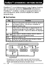
•  While transmitting (holding the 

PTT

 switch or speaking with 

VOX

 enabled), always keep the antenna 

and the radio at least 3 cm (1 3/16 inches) from your body or face, as well as from any bystanders.  A 

LED on the top of the radio shows red when the transmitter is operating in both 

PTT 

and 

VOX

 modes.

•  Do not transmit for more than 50% of the total transceiver use time; transmitting over 50% of the total use 

time may exceed the limits in accordance to the FCC RF exposure requirements.  Nominal transceiver 

operation is 5% transmission time, 5% reception time, and 90% stand-by time.

•  Use only the specified antenna for this transceiver; this may be either the antenna provided with the 

transceiver or another antenna authorized by 

Kenwood

.

Use only 

Kenwood 

authorized accessories (antennas, battery packs, belt clips, Speaker/ Mics or 

headsets etc.): When worn on the body, always place the radio in a 

Kenwood

 recommended clip or 

carrying case meant for this product. The use of other than recommended or approved body- worn 

accessories may result in RF exposure levels which exceed the FCC’s occupational/ controlled 

environment RF exposure limits.

To ensure that your exposure to RF EME is within the FCC limits for occupational use, you must 

observe and adhere to the above points.

Electromagnetic Interference Compatibility

Electronic devices are susceptible to electromagnetic interference (EMI) if they are not adequately 

shielded or designed for electromagnetic compatibility.  Because this transceiver generates RF 

energy, it can cause interference to such equipment.

•  Turn OFF your transceiver where signs are posted to do so.  Hospitals and health care facilities use 

equipment that is sensitive to electromagnetic radiation.

•  Turn OFF your transceiver while on board an aircraft when so instructed.  Use of the transceiver must 

be in accordance with airline regulations and/or crew instructions.

B59-2546-00

Summary of Contents for FM Transceiver TK-481

Page 1: ... B62 1483 10 K K2 K3 K4 09 08 07 06 05 04 03 02 01 INSTRUCTION MANUAL VHF FM TRANSCEIVER UHF FM TRANSCEIVER TK 280 TK 380 800 MHz FM TRANSCEIVER 900 MHz FM TRANSCEIVER TK 480 TK 481 ...

Page 2: ...TK 280 VHF FM Transceiver TK 380 UHF FM Transceiver TK 480 800 MHz FM Transceiver TK 481 900 MHz FM Transceiver NOTICES TO THE USER Government law prohibits the operation of unlicensed radio transmitters within the territories under government control Illegal operation is punishable by fine and or imprisonment Refer service to qualified technicians only SAFETY It is important that the operator is ...

Page 3: ...t occur in a particular installation If this equipment does cause harmful interference to radio or television reception which can be determined by turning the equipment off and on the user is encouraged to try to correct the interference by one or more of the following measures Reorient or relocate the receiving antenna Increase the separation between the equipment and receiver Connect the equipme...

Page 4: ...Display 7 PROGRAMMABLE AUXILIARY FUNCTIONS 8 OPERATION OVERVIEW 10 Trunking Format 10 Conventional Format TK 280 TK 380 Only 10 OPERATING BASICS 11 Switching Power ON OFF 11 Adjusting the Volume 11 Selecting a System Group Channel 11 Time out Timer TOT 12 TRUNKED OPERATION Trunking Format 13 Placing a Dispatch Call 13 Receiving a Dispatch Call 13 Placing a Telephone Call Keypad Models Only 14 Rece...

Page 5: ...Transmitting 19 Receiving 19 SCAN Conventional Format 20 Priority Scan 20 2 TONE SIGNALLING Conventional Format 21 FleetSync ALPHANUMERIC 2 WAY PAGING FUNCTION 22 Key Functions 22 Selcall Selective Calling 23 Status Message 25 Optional Short Messages Feature 27 DTMF DUAL TONE MULTI FREQUENCY CALLS 28 Making a DTMF Call Keypad Models Only 28 DTMF Signalling 30 DBD Dead Beat Disable 30 AUDIBLE USER ...

Page 6: ...maged during shipment file a claim with the carrier immediately Supplied Accessories m e t I r e b m u N t r a P y t i t n a u Q a n n e t n A 0 8 4 K T X X 6 3 6 0 0 9 T 1 1 8 4 K T X X 0 4 6 0 0 9 T i N k c a p y r e t t a b d C 2 K K 1 8 4 K T 0 8 4 K T y l n o s e p y t X X 0 0 9 0 9 0 W 1 p i l c t l e B X X 8 5 6 0 9 2 J 1 p a c r o t c e n n o c l a r e v i n U X X 3 6 3 0 9 0 B 1 t e s w e...

Page 7: ... transceiver Installing Removing the Battery Pack Do not recharge the battery pack if it is already fully charged Doing so may cause the life of the battery pack to shorten or the battery pack may be damaged After recharging the battery pack disconnect it from the charger If the charger power is reset turned on after being turned off recharging will start again and the battery pack will become ove...

Page 8: ... and turning it clockwise until secure Installing the Belt Clip If necessary attach the belt clip using the two supplied 3 x 6 mm screws Note If the belt clip is not installed its mounting location may get hot during continuous transmission or when left sitting in a hot environment Installing the Antenna ...

Page 9: ... connector using the supplied 4 x 6 mm screw Installing the Cover over the Universal Connector Installing the Optional KMC 25 Speaker Microphone 1 Insert the guide of the speaker microphone connector into the groove of the universal connector 2 Secure the connector in place using the attached screw ...

Page 10: ...MF keypad 1 q q q q q Antenna connector Connect an antenna here w w w w w Rotary encoder Rotate this encoder to activate its programmable function System or Group Up Down in Trunking Format and Group or Channel Up Down in Conventional Format For further details contact your dealer Microphone Speaker ...

Page 11: ...To Talk switch Press this switch then speak into the microphone to call a station i i i i i PF Programmable Function key Press to activate its auxiliary function page 8 o o o o o Transmit Battery low indicator This red LED lights during transmission If programmed by your dealer when the battery pack power is low the LED flashes during transmission Replace or recharge the battery pack 0 0 0 0 0 S A...

Page 12: ...a r e p O e h t s t h g i L e g a s s e m a e v i e c e r u o y n e h w s e h s a l F y r o m e m k c a t s e h t n i d e r o t s s i e g a s s e m a n e h w s r e b m u n l e n n a h c d n a p u o r g m e t s y s e h t s y a l p s i D d n a p u o r g m e t s y s m a r g o r p n a c r e l a e d r u o Y e c a l p n i s r e t c a r a h c 0 1 o t p u h t i w s e m a n l e n n a h c a s a d e s u s i ...

Page 13: ...t is available for only the TK 280 and TK 380 models n o i t c n u F l a n o i t n e v n o C t a m r o F g n i k n u r T t a m r o F l e T o t u A o N s e Y X U A 1 s e Y s e Y n w o D l e n n a h C s e Y o N p U l e n n a h C s e Y o N T O B D I F M T D s e Y s e Y T O E D I F M T D s e Y s e Y r e t c a r a h C y a l p s i D s e Y s e Y y c n e g r e m E 2 s e Y s e Y n o i t c n u F s e Y s e Y...

Page 14: ...A l e D n a c S s e Y s e Y e t e l e D y r a r o p m e T n a c S o N s e Y S P G d n e S 3 s e Y s e Y n o i t a u n e t t A P S 4 s e Y s e Y n w o D m e t s y S o N s e Y p U m e t s y S o N s e Y r e l b m a r c S 5 s e Y s e Y d n u o r A k l a T s e Y o N t c e n n o c s i D L E T o N s e Y 1 This function can be selected only when the Scrambler ANI board has not been installed 2 This functi...

Page 15: ...roups in each system The transceiver can be used in both trunked mode and conventional mode Systems groups and their functions are programmed by your dealer Conventional Format TK 280 TK 380 Only This format can handle up to 250 groups with 250 channels in each group The transceiver can be used only in conventional mode Groups channels and their functions are programmed by your dealer ...

Page 16: ... S key If you enter the wrong password an error tone sounds and the transceiver remains locked The password can contain a maximum of 6 digits Adjusting the Volume Rotate the Power switch Volume control to adjust the volume Clockwise increases the volume and counterclockwise decreases it Selecting a System Group Channel Select the desired system and group Trunking Format using the encoder and the k...

Page 17: ...l for an extended period of time If you continuously transmit for a period of time that exceeds the programmed time the transceiver will stop transmitting and an alert tone will sound To stop the tone release the PTT switch Your dealer can program the TOT time in the range of 15 seconds to 10 minutes ...

Page 18: ...ng into the microphone Release the PTT switch to receive For best sound quality at the receiving station hold the microphone approximately 1 5 inches 3 4 cm from your mouth Receiving a Dispatch Call 1 Select the desired system and group using the encoder and the System or Group keys If the Scan function has been programmed you can switch it ON or OFF as desired 2 When you hear the dispatcher s voi...

Page 19: ...switch and speak into the microphone Release the PTT switch to receive Only one person can speak at a time 5 To end the call press and hold the PTT switch then press the key or the key programmed as Tel Disconnect Receiving a Telephone Call Keypad Models Only 1 Select the desired system and group using the encoder and the System or Group keys If the Scan function has been programmed you can switch...

Page 20: ...ecomes free 3 Press the PTT switch and speak into the microphone Release the PTT switch to receive For best sound quality at the receiving station hold the microphone approximately 1 5 inches 3 4 cm from your mouth Receiving 1 Select the desired system and group using the encoder and the System or Group keys If the Scan function has been programmed you can switch it ON or OFF as desired 2 When you...

Page 21: ...m and group digits appear Press the PTT switch and speak into the microphone to respond to the call The transceiver will continue scanning after a predetermined time delay if the PTT switch is released and no further signal is received Scanning Trunked Systems When scanning trunked systems the revert groups and the groups not locked out of the scanning sequence are scanned See GROUP SCAN on page 1...

Page 22: ...n Reverts which can be programmed by your dealer are available Last Called Revert The last system group received is assigned as the new revert system and group Last Used Revert The last system group responded to is assigned as the new revert system and group Selected The last system group selected is assigned as the new revert system and group Selected Talkback If the system group has been changed...

Page 23: ...by your dealer on request It scans the revert groups as well as groups that are allowed to be scanned When a call is received the group indicator shows the group number and that group becomes the revert group Simply press the PTT switch to respond to the call You can also perform Group Scan while using a priority channel Please contact your dealer for information concerning Priority Scan ...

Page 24: ...it becomes free 3 Press the PTT switch and speak into the microphone Release the PTT switch to receive For best sound quality at the receiving station hold the microphone approximately 1 5 inches 3 4 cm from your mouth Receiving 1 Select the desired group and channel using the encoder and the Group or Channel keys If the Scan function has been programmed you can switch it ON or OFF as desired 2 Wh...

Page 25: ...e group and channel digits appear Press the PTT switch and speak into the microphone to respond to the call The transceiver will continue scanning after an adjustable time delay if the PTT switch is released and no further signal is received When the displayed group is not locked out of the scanning sequence the add indicator will appear on the display Priority Scan The priority channel must be pr...

Page 26: ...nd the squelch opens pressing the key programmed as Monitor will cancel the connection If your dealer programmed Transpond for 2 Tone Signalling your transceiver will automatically send an acknowledgment signal to the station that called you with the correct 2 Tone signal Transpond does not function when you are called as a Group call If your dealer programmed Tone Alert for 2 Tone Signalling your...

Page 27: ...n o e l b a l i a v a s i y e k y l n o s l e d o m d a p y e k S e h t n e e w t e b e l g g o t o t e d o M k c a t S n i e l i h w s s e r P d n a s s e r P D I s r e l l a c e h t d n a e g a s s e m d e v i e c e r d e y a l p s i d e h t e t e l e d o t d n o c e s 1 n a h t e r o m r o f d l o h e g a s s e m t t t t tB Cs s s s s a t c e l e s o t e d o m s u t a t S r o l l a c l e S n i ...

Page 28: ... tB or Cs key to select the ID of the station you want to call You can also enter digits by using the DTMF keypad if Manual Dial is enabled Press to erase an incorrect digit 4 Press the PTT switch and begin your conversation To Receive An alert tone will sound the transceiver will automatically enter Selcall Mode and the calling station s ID will appear when a Selcall is received To respond to the...

Page 29: ... An ID code is a combination of a 3 digit Fleet number and a 4 digit ID number Each transceiver must have its own Fleet and ID number Enter a Fleet number 100 349 to make a group call Enter an ID number 1000 4999 to make an individual call in your fleet Enter a Fleet number followed by an ID number to make an individual call in your desired fleet Inter fleet call Select ALL Fleet and ALL ID to mak...

Page 30: ...ill be cleared when the transceiver power is turned OFF To Transmit 1 Select your desired system and group or group and channel 2 Press the A key to enter Selcall Mode 3 Press the tB or Cs key to select the ID of the station you want to call You can also enter digits by using the DTMF keypad if Manual Dial is enabled Press to erase an incorrect digit 4 Press the A or key to enter Status Mode 5 Pre...

Page 31: ...ith the message number S Status appears with the number 2 Press the tB or Cs key to select the message you want to view if more than one message is stored in the stack memory 3 Press the S key to toggle between the message and the caller s ID 4 To erase the message press and hold the S key for more than 1 second Automatic Status Response If you pre select a status number and then leave the transce...

Page 32: ... Feature Received short messages maximum of 48 characters are displayed the same as Status messages page 24 however only 4 short messages can be stored in the stack memory M Message and the message number appear with the message ...

Page 33: ...e front panel keypad The corresponding DTMF tones sound each time you press a key If you release the PTT switch transmit mode will end even if the complete number has not been sent If your dealer has activated the Keypad Auto PTT function you need not hold down the PTT switch while pressing the keys on the keypad in Conventional systems The DTMF code will be sent automatically when you press a key...

Page 34: ...Releasing the PTT switch before a connection is established will stop the transmission from occuring If you are using the transceiver in a RIC Repeater Inter Connect Trunking system the DTMF code is transmitted after a connection with the telephone system is established If you press the key programmed as Auto Tel instead of the PTT switch the call will automatically connect to the repeater and the...

Page 35: ...h a code that matches your signalling reset code When making a call on a group programmed with a DTMF signalling code the signalling indicator will light and the squelch will open DBD Dead Beat Disable Depending on how your dealer programs your transceiver when you receive a call containing a DBD code either transmit mode or receive and transmit modes will be disabled When a DBD code is received a...

Page 36: ...s e Y y a l e D o N s e Y y n e D o N s e Y e d o M k c a B g n i R m e t s y S e e r F e d o M h c r a e S m e t s y S o N s e Y l l a C p u o r G s e Y s e Y l l a C l a u d i v i d n I s e Y s e Y t p e c r e t n I o N s e Y r o r r E t u p n I y e K s e Y s e Y A s s e r P y e K s e Y s e Y B s s e r P y e K s e Y s e Y C s s e r P y e K s e Y s e Y t n e m e e r g A d r o w s s a P s e Y s e ...

Page 37: ... n o i t n e v n o C t a m r o F g n i k n u r T t a m r o F g n i g n i R o N s e Y r e v O l l o R s e Y s e Y h c r a e S m e t s y S o N s e Y d n E h c r a e S m e t s y S o N s e Y d n o p s n a r T s e Y s e Y ...

Page 38: ...l MIC Input 1 8 kΩ I 6 ME External MIC GND GND 7 PTT External PTT Input High Impedance I 8 PF Programable Function Key Input High Impedance I 9 NC Not used 10 E GND GND 11 5M 5V power supply output 5V 12 TXD Serial Data Output CMOS O 13 RXD Serial Data Input CMOS I 14 NC Not used Antenna Terminal 50 Ω impedance Battery Terminal The battery terminal uses a spring plate The negative terminal connect...

Page 39: ...nce of their employment may not be fully aware of the potential for exposure or cannot exercise control over their exposure The following list provides you with the information required to ensure that you are aware of RF exposure and of how to operate this transceiver so that the FCC RF exposure limitations are not exceeded While transmitting holding the PTT switch or speaking with VOX enabled alw...

Reviews: