background image

DMF-5020/DMF-3020/MD-203 (En)

46

Editing

2

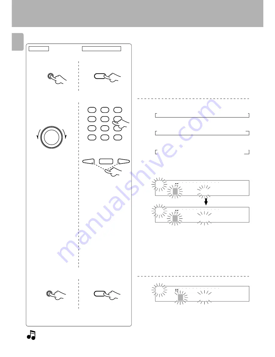
The characters can be switched by rotating the JOG DIAL.

A to Z and space (a blank character):

a to z and space:

0 to 9, symbols, preset titles (x 9):

One of the following character groups can be selected.

A to Z and space (a blank character):

a to z and space:

0 to 9, symbols, preset titles (x 9):

Input the title.

1

Select a character group.

2

Select a character.

To return

To advance

Example of new title input:

Initial display

÷

The display can be scrolled so that any character (in a single group) can
be selected.

÷

Characters can also be selected directly from the remote control unit by
using the numeric keys.
(Example: Each press of the 

2

 key switches characters in order of

=

 B 

=

 C

.)

÷

The cursor can be moved to the left and right with the 

1

 and  

¡

 keys.

÷

Pressing the 

TITLE SEARCH

 key during title input switches the input

mode between the “overwrite mode” and “insert mode”.

Selected character

This procedure is continued on next page.

3

Set the selected character.

Repeat steps

 1

 to 

3

 till all of the title characters have been

input.

÷

Pressing the 

EDIT/SPACE

 key inserts a blank space character.

¤ A

¤ B

¤ C

¤ D

¤ E

¤ F

¤ E E E E E

¤

¤ a

¤ b

¤ c

¤ d

¤ e

¤ f

¤ E E E E E

¤

¤ 0

¤ 1

¤

E E E

¤ 9

¤

¤ !

¤

h E E E

PRE9

'

E E E

' PRE1

' _

' ^

' @

' ?

OVER (

dB)

R

L

TITLE

A B C

|

15

9

12

7

5

1

3

40

30

21

18

0

SEARCH

PGM

MONITOR

ANALOG

32kHz

2

1

3

48kHz

44.1kHz

DIGITAL

OVER (

dB)

R

L

TITLE

J K L M

|

15

9

12

7

5

1

3

40

30

21

18

0

SEARCH

PGM

MONITOR

ANALOG

32kHz

2

1

3

48kHz

44.1kHz

DIGITAL

OVER (

dB)

R

L

TITLE

J K L M

|

K

15

9

12

7

5

1

3

40

30

21

18

0

SEARCH

PGM

MONITOR

ANALOG

32kHz

2

1

3

48kHz

44.1kHz

DIGITAL

or

Main unit

Remote control unit

CHARA.

P.MODE

1

GHI

4

PRS

7

& (   ) - /

+100

ABC

2

JKL

5

TUV

8

QZ

0

DEF

3

MNO

6

WXY

9

’ , : ? !

+10

4

¢

£

SET

SET

4


¢

JOG DIAL

4

¢

REC MODE/CHARAC.

Summary of Contents for DMF-3020

Page 1: ...4 00 01 MA K P T MC 9806 DMF 5020 DMF 3020 MD 203 INSTRUCTION MANUAL This instruction manual is used to describe multiple models listed above Model availability and features functions may differ depending on the country and sales area ...

Page 2: ...the fuse and dispose of the plug immediately to avoid a possible shock hazard by inadvertent connection to the mains supply IMPORTANT The wires in the mains lead are coloured in accordance with the following code Blue Neutral Brown Live Do not connect those leads to the earth terminal of a three pin plug For the United Kingdom CAUTION TO REDUCE THE RISK OF ELECTRIC SHOCK DO NOT REMOVE COVER OR BAC...

Page 3: ...ording when the track starts SOUND SYNCHRO REC 26 Automatically pausing recording when the track ends REC AUTO PAUSE 26 Starting recording from the sound before the current sound MEMORY REC 26 Recording ANALOG input 27 ANALOG recording 27 Recording DIGITAL input 29 DIGITAL recording 29 Synchro recording with CD playback 31 DIGITAL recording and SCMS 31 Editing 32 Selecting the editing function typ...

Page 4: ... person or company receiving the unit can file a claim against the carrier for shipping damage We recommend that you retain the original carton and packing materials for use should you transport or ship the unit in the future Keep this manual handy for future reference Remote control unit 1 RC M0705 For DMF 5020 Batteries 2 R03 AAA size batteries For RC M0705 R6 AA size batteries For RC M0302 Chec...

Page 5: ...ng hour mode of DAT For recording of A mode broadcasting of BS tuner In addition to the conventional editing functions MOVE DIVIDE COMBINE and ERASE this unit provides more versatile editing functions such as the QUICK MOVE function for moving desired tracks at once or the QUICK ERASE function for erasing desired tracks at once D R I V E for high quality playback For DMF 5020 only Versatile editin...

Page 6: ...liance should not be placed in a built in installation such as a bookcase or rack unless proper ventilation is provided or the manufacturer s instructions have been adhered to 5 Water and moisture The appliance should not be used near water for example near a bathtub washbowl kitchen sink laundry tub in a wet basement or near a swimming pool etc Never pull or stretch the cord 6 Temperature The app...

Page 7: ...nit size of grounding conductors location of antenna discharge unit connection to grounding electrodes and requirements for the grounding electrode See Figure 18 Power lines An outside antenna system should not be located in the vicinity of overhead power lines or other electric light or power circuits or where it can fall into such power lines orcircuits Wheninstallinganoutsideantennasystem extre...

Page 8: ...ollowing operations 1 Set the POWER key to ON without loading a Mini Disc Check that no disc is present in the unit 2 Wait a few seconds and verify that the display shown appears 3 Set the POWER key to OFF Storage position Do not leave Mini Discs in place where the temperature and or humidity are extremely high for example in a place subject to direct sunlight Slide close Recording enabled Slide o...

Page 9: ...riable depending on the surrounding environment In case of long hours of power failure or slipping out of the power cord the data related to recording and editing that is usually recorded at the moment the Mini Disc is ejected may be cleared or destroyed before it is written in the Mini Disc Remember that the data lost cannot be recovered After recording or editing be sure to eject the Mini Disc s...

Page 10: ... connection cords without removal of the power cord can cause malfunctions or damage to the unit Malfunction of microprocessor If operation is not possible or erroneous display ap pears even though all connections have been made properly reset the microprocessor referring to In case of difficulty Q When connecting the audio cords cords with pin plugs on each end insert the white plugs into the L L...

Page 11: ...ver when you start playback from this unit Synchronized Recording When recording a CD after setting the amplifier s input selector to CD starting playback on the CD player allows to start recording automatically in an interlocked operation Do not operate the CD player during recording of a digital source other than CD otherwise malfunction may occur Synchronized recording is not possible while the...

Page 12: ...tion is referred to as the standby mode of the unit While the unit is in the standby mode it can be turned ON from the remote control unit Standby mode Names and functions of parts Display Main unit Display TITLE and SEARCH indicators MONO indicator PGM Program indicator Peak level indicators Listening through headphones Plug the stereo headphones with standard plug available in audio stores into ...

Page 13: ...REC MODE Press to switch the recording setting adjustment modes record modes ON OFF CHARAC Press to select a character group during the title input operation Description of main unit keys Names and functions of parts SET key For use in setting the editing result and input title in memory When pressed in the recording pause mode the MEMORY REC function is set and recording starts from the sound app...

Page 14: ... Press to monitor the sound being input from the source while the unit is in stop mode METER key Press to switch the level meter display contents RANDOM key Press to initiate the random play mode REPEAT key Press to switch the repeat modes for repeat playback 1ON STANDBY key Press to turn the unit between ON and STANDBY modes 6Recording related keys REC MODE key Press to switch the recording setti...

Page 15: ...automatically at the point where the track number changes during playback When pressed in the recording or record ingstandbymode theAUTORECPAUSE mode is turned on AUTO MANU key Selects whether the track numbers are to be marked automatically during re cording AUTO or to be marked manu ally after it MANUAL MONITOR key Press to monitor the sound being input from the source while the unit is in stop ...

Page 16: ...vice life may be short 2 When the remote controllable distance becomes short replace all batteries with new ones 3 If direct sunlight or the light of a high frequency fluorescent lamp inverter type etc is incident to the remote sensor malfunction may occur In such a case change the installation position to avoid malfunction When pressing more than one remote control keys successively press the key...

Page 17: ...ini Disc recorded in the monaural long play mode As the monaural long play mode requires half the amount of data required for stereo mode recording the playing time recording time of the disc is doubled to max 148 minutes from that in the stereo mode A Mini Disc recorded in the monaural long play mode cannot be played normally with equipment which is not compatible with monaural playback In case n...

Page 18: ... being played Elapsed time of track being played Characters flow toward the left 1 Put the MD recorder in stop mode 2 Check the track mode PGM goes off Playback of Mini Disc OVER dB R L TITLE 0 0 1 T I T L E 15 9 12 7 5 1 3 40 30 21 18 0 SEARCH PGM MONITOR ANALOG 32kHz 2 1 3 48kHz 44 1kHz DIGITAL To smaller track No To larger track No OVER dB R L TITLE 0 0 3 T I T L E 15 9 12 7 5 1 3 40 30 21 18 0...

Page 19: ...t the desired track number Playback from desired track PGM goes off Press the numeric keys as shown below To enter track No 23 0 0 3 To enter track No 40 0 0 0 0 To enter track No 212 100 100 0 2 To start playback directly from a part of a track Early part of track No 7 7 2 7 2 Middle part of track No 7 7 5 7 5 Latter part of track No 7 7 8 7 8 Middle part of current track 5 5 If a track NO which ...

Page 20: ...ch is started during play pause the disc can be searched at a high speed but sound is not output When the reverse search is started during the program mode and the beginning of the current track is attained it will be played from the beginning To stop playback Ejecting the disc Mini Disc has been ejected AUTO PAUSE key Remote control unit only When the AUTO PAUSE key is pressed playback pauses aft...

Page 21: ...period has attained 256 minutes or more Tracks will be played in the order they are programmed When the 4 or key is pressed during playback tracks will be skipped in the direction of the pressed key Total remaining time of the programmed tracks Track No being played The input operation is aborted if the CHARA P MODE key is not pressed while the indicator is blinking PGM lights up Selected track Pr...

Page 22: ...number of the track that has been cleared is displayed Example when P 14 has been cleared Clearing tracks from the end Press in stop mode Clearing all tracks Press in stop mode Press in stop mode or Programming Remote control unit The 0 key is only provided on the DMF 5020 OVER dB R L COPY 0 1 4 P 0 3 15 9 12 7 5 1 3 40 30 21 18 0 SEARCH PGM MONITOR ANALOG 32kHz 2 1 3 48kHz 44 1kHz DIGITAL OVER dB...

Page 23: ...op repeated playback Press the REPEAT key again The REPEAT indicator goes off and the playback following the current mode PROGRAM of the MD player starts To stop repeated playback Press the REPEAT key again REPEAT lights up PGM lights up Repeated playback Each press switches the mode 1 Track mode PGM goes off 2 Program mode PGM lights up Each press switches the mode 1 Track mode PGM goes off 2 Pro...

Page 24: ...d REC AUTO PAUSE settings are turned on This setting is convenient when recording a CD which has been recorded in live or which contains very low level sound such as a classical music CD Press in stop mode Press to monitor the sound being input from the source while the unit is in stop mode When the REC INPUT is DIGITAL the sampling rate 48 kHz 44 1 kHz 32 kHz of the input digital signal can be di...

Page 25: ...l is set for all the above functions The initial setting is LEVEL 0 The level can be set between 3 and 3 OVER dB R L T I M E 0 2 S E C 15 9 12 7 5 1 3 40 30 21 18 0 SEARCH PGM MONITOR ANALOG 32kHz 2 1 3 48kHz 44 1kHz DIGITAL Setting display Initial display When AUTO CUT is displayed The AUTO CUT function sets SOUND SYNCHRO REC to the pause mode automatically when the sound falls below a certain le...

Page 26: ...ecording when the track ends REC AUTO PAUSE Recording is automatically paused when the sound input is below a certain level for over 3 seconds or when the track number changes during digital recording of a CD This function comes in handy when you only want to record one track from the CD Press while in the recording or recording pause mode The sound detection level can be adjusted with the REC MOD...

Page 27: ...e mode 1 ANALOG Analog stereo mode 2 DIGITAL 1 Optical input mode 3 DIGITAL 2 Coaxial input mode 4 MONO Analog monaural long play mode ANALOG lights up 1 Open the write protect tab of the Mini Disc to make it recordable 8 2 Load the Mini Disc 3 Check the remaining recording time o 4 Set the amplifier s input selector to the source to be recorded ANALOG recording For details on the setting adjustme...

Page 28: ...e Mini Disc When the EDIT SPACE key is pressed during recording a track number is inserted in that position After recording eject the Mini Disc Start recording Information is being written Mini Disc has been ejected Select AUTO or MANUAL Remote control unit only Adjust the recording level Main unit only To increase level To decrease level 1Press the 8 key 2Play the source to be recorded from the b...

Page 29: ...or to the source to be recorded Select AUTO or MANUAL Remotecontrol unit only Select one of DIGITAL 1 2 Each press switches the mode 1 REC MODE off 2 REC MODE on Each press switches the mode 1 ANALOG Analog stereo mode 2 DIGITAL 1 Optical input mode 3 DIGITAL 2 Coaxial input mode 4 MONO Analog monaural long play mode Each press switches the mode 1 goes off AUTO Track numbers are marked automatical...

Page 30: ...ncremented by 1 at the moment the CD starts to play This is caused by a signal contained in the digital signal component of the CD Unnecessary track numbers can be erased by following the procedure for Erasing the track being played TRACK ERASE q While WRITING is displayed do not apply shock or vibration to the unit because information is being written on the Mini Disc Play the source to be record...

Page 31: ...T A mode broadcasting of BS tuner etc In general high quality recording based on digital signal transmission is available only when the sampling frequency of the source equipment matches that of the recorder equipment However this unit incorporates a sampling rate converter so that it can also record digital signals sampled at 48 kHz and 32 kHz by converting their sampling frequency into the sampl...

Page 32: ...ible to edit a playback only Mini Disc Editing is not possible while the PGM indicator is lit Moving the track being played TRACK MOVE Moving several tracks at a time QUICK MOVE fi Reordering tracks by moving them Selecting the editing function type Erasing one or more track at a time QUICK ERASE e Erasing the track being played TRACK ERASE q ALL ERASE e D C B A D A B C D C B A D C B A C B A Z C B...

Page 33: ...lection Editing is aborted if no operation has been performed for 8 seconds 1 Play the track to be moved 2 Press the EDIT SPACE key to switch the editing mode on Moving the track being played TRACK MOVE To increase track No Destination track No Track to be moved OVER dB R L M O V E 15 9 12 7 5 1 3 40 30 21 18 0 SEARCH PGM MONITOR ANALOG 32kHz 2 1 3 48kHz 44 1kHz DIGITAL OVER dB R L 0 0 1 0 0 2 15 ...

Page 34: ...perform the following key operations before ejecting the disc After canceling the editing operation can be restarted from the beginning Display after execution EDIT NOW When editing is in progress COMPLETE When editing is completed successfully CAN T EDIT When editing is incomplete Mini Disc has been ejected Information is being written Image of track moving Selected destination Selected destinati...

Page 35: ...ing the 1 key or key of the remote control unit 1 Select a track number 2 Set the selection To increase track No To decrease track No Repeat steps 1 and 2 until all tracks have been ar ranged in the desired order 1 Put the MD recorder in stop mode 2 Press the EDIT SPACE key to switch the editing mode on Moving several tracks at a time QUICK MOVE Title scrolling Next track No 1 2 3 Editing is abort...

Page 36: ...tion EDIT NOW When editing is in progress COMPLETE When editing is completed successfully CAN T EDIT When editing is incomplete Image of track insertion Display when tracks are moved between two track Nos Display when tracks are moved at the top of all tracks Track No Mini Disc has been ejected Information is being written 0 1 OVER dB R L P O T 0 15 9 12 7 5 1 3 40 30 21 18 0 SEARCH PGM MONITOR AN...

Page 37: ...inues till the next track the first track if it is started in the last track but the part in the next track cannot be divided by TRACK DIVIDE Editing is aborted if no operation has been performed for 8 seconds Preparation When preview is not required press the ENTER key once so that ok is displayed then go to step 3 1 Play the MD track to be divided 2 Press the EDIT SPACE key to switch the editing...

Page 38: ...half Divided track first half Should be approx 2 sec or longer Image of track division Image of preview Display after execution EDIT NOW When editing is in progress COMPLETE When editing is completed successfully CAN T EDIT When editing is incomplete While WRITING is displayed do not apply shock or vibration to the unit because information is being written on the Mini Disc Up to 255 track numbers ...

Page 39: ...ing played and the track immediately after it will be combined If the operation is started during playback it pauses automatically Preparation To combine the track with the next track to it go to step 3 Track being played To combine track Nos 5 and 7 Combining the track being played TRACK COMBINE To decrease track No To increase track No Some functions are limited due to the restrictions im posed ...

Page 40: ...on Should be approx 2 sec or longer Execute the track combine operation Eject the Mini Disc While WRITING is displayed do not apply shock or vibration to the unit because information is being written on the Mini Disc Display after execution EDIT NOW When editing is in progress COMPLETE When editing is completed successfully CAN T EDIT When editing is incomplete Mini Disc has been ejected Informati...

Page 41: ...n has been performed for 8 seconds Display after execution EDIT NOW When editing is in progress COMPLETE When editing is completed successfully CAN T EDIT When editing is incomplete Confirm that the track has been erased Preparation Erasing the track being played TRACK ERASE 1 Select ERASE 2 Set the selection The modes are switched by rotating the JOG DIAL 1 DIVIDE Dividing a track 2 COMBINE Combi...

Page 42: ...Mini Disc has been ejected While WRITING is displayed do not apply shock or vibration to the unit because information is being written on the Mini Disc Track Nos are adjusted Track to be erased Image of track erasure N O D I S C WRITING EJECT Note Note Note A B D 1 2 4 3 C A B 1 2 3 D 4 0 ...

Page 43: ... Confirmation of all track erasure 1 Select a track number to be erased 2 Set the selection Selected track OVER dB R L E R Q A S E 15 9 12 7 5 1 3 40 30 21 18 0 SEARCH PGM MONITOR ANALOG 32kHz 2 1 3 48kHz 44 1kHz DIGITAL OVER dB R L 5 B C A 0 0 15 9 12 7 5 1 3 40 30 21 18 0 SEARCH PGM MONITOR ANALOG 32kHz 2 1 3 48kHz 44 1kHz DIGITAL OVER dB R L 0 0 6 5 0 0 15 9 12 7 5 1 3 40 30 21 18 0 SEARCH PGM ...

Page 44: ...ration is not possible If DISC ERROR is displayed with a Mini Disc which has been known to be normal re load the Mini Disc before proceeding to the ALL ERASE operation This may makes it possible to read the Mini Disc contents Display after execution EDIT NOW When editing is in progress COMPLETE When editing is completed successfully CAN T EDIT When editing is incomplete Erasing desired tracks Eras...

Page 45: ...rted if no operation has been performed for 8 seconds To edit a disc title Select DISC To edit a track title Select the desired track number To edit the preset titles Select the desired preset number To erase both disc and track titles 2 Set the selection To abort operation press the TITLE INPUT key again To input a title go to step 2 To change or delete a title go to step 3 Editing titles To retu...

Page 46: ...d right with the 1 and keys Pressing the TITLE SEARCH key during title input switches the input mode between the overwrite mode and insert mode Selected character This procedure is continued on next page 3 Set the selected character Repeat steps 1 to 3 till all of the title characters have been input Pressing the EDIT SPACE key inserts a blank space character A B C D E F E E E E E a b c d e f E E ...

Page 47: ...elected character The display can be scrolled so that any character in a single group can be selected Characters can also be selected directly from the remote control unit by using the numeric keys Example Each press of the 2 key switches characters in order of A B C The cursor can be moved to the left and right with the 1 and keys All characters of a title can be changed or erased by repeating st...

Page 48: ...the Mini Disc Scrolling the display There may be cases in which the amount of information is too large to be displayed at a time during the title input operation etc In such a case pressing the 1 or key repeatedly allows to move the displayed characters to the left or right so that other information which has been hidden can be displayed This leftward or rightward movement of the display character...

Page 49: ...splayed if the disc has a title 2 REMAIN Remaining recording time of disc 3 TITLE The Mini Disc title is displayed The level meter display contents can be switched over in cycle 1 Normal display The scale around 0 dB is set finely in this mode which is suitable for normal recording rock or playback pop music 2 Wide display The scale is set almost evenly from 0 dB to 30 dB in this mode which is sui...

Page 50: ...ake preparations For timer recording be sure to set the write protect tab to enable recording 8 For timer recording be sure to check the remaining recording time o 2 5 After having set the timer be careful not to press the ON STANDBY key of the remote control unit to ON otherwise the timer operation would be activated Set the timer so that the tuner reception can be started at the desired time of ...

Page 51: ... of an editing operation may sometimes be impossible to be combined with another track As recording is performed on a minimum recording basis of 2 seconds the displayed time may not coincide with the consumed disc capacity Sound interruption may occur due to a combination of various factors and it is not a malfunction A short track may be created depending on the contents of the recorded source CD...

Page 52: ... editing Release the WRITE PROTECT condition 8 Load a recordable Mini Disc This unit is not loaded with disc The digital cord or optical fiber cable is not locked in position or connected incompletely or not connected An attempt is made to record digital signal from a source while its digital copy has been prohib ited by SCMS The digital signal being input is not an audio signal There is no record...

Page 53: ...ited by SCMS The recording level is too low in case of analog recording A playback only disc has been loaded The disc does not have a recordable area The REC INPUT key is not set to the actual input source If the amplifier is connected to this unit through a system control cord the amplifier s input selector is set to the MD input The recording level has not been adjusted A disc in which distorted...

Page 54: ...kg 8 8 lb 1 KENWOOD follows a policy of continuous advancements in development For this reason specifications may be changed without notice 2 The full performance may not be exhibited in an extremely cold location under a water freezing temperature Notes Notes DMF 3020 MD 203 Format System Minidisc digital audio system Laser Semiconductor laser Recording method Field modulation overwrite method Au...

Page 55: ...unications if it is not installed and used in accordance with the instructions However there is no guarantee that interference will not occur in a particular installation If this equipment does cause harmful interference to radio or television reception which can be determined by turning the equipment off and on the user is encouraged to try to correct the interference by one or more of the follow...

Page 56: ...found on the back of the unit in the spaces designated on the warranty card and in the space provided below Refer to the model and serial numbers whenever you call upon your dealer for information or service on this product Model Serial Number ...

Reviews: