


5
DMC-K3
CIRCUIT DESCRIPTION
1. Main microprocessor : uPD784036GC831 (X33 : IC5)
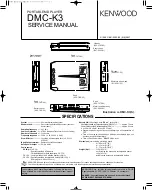
1-1 Microprocessor periphery block diagram(X33)
1-2 Pin description
IC9
IC7
RE/SERVO
CXA2523AR
DSP/ATRAC
CXD2655BR
SERIAL XLAT XRST FOK SQSY SENS
Q6
BEEP MIXER
IC5
Q17
XSTBY
BEEP
BASS BOOST
BassBoost
IC12
SEIN
MUTE SW
IC8
u-COM
HEAD PHONES AMP
MOTOR DRIVER
S1-S3
uPD784036GC
PSW
LA4801V
BD6601KVT
EPDO
EPDI
IC10
BEMFU,V,W
EPCS
E2PROM
EPSK
AK93C45AV
ED1
com
SEG1-19
LCD(SET)
SP PWS CHG1 CHG2 ADP CHGOK BATT
POWER SUPPLY CONTROL/RECHARGEABLE CIRCUIT
Pin No.
Name
I/O
Description
Function
H/L
1
XLAT
O
DSP IC (CXD2655BR) LATCH signal
2
XRST
O
DSP IC (CXD2655BR) HARD RESET signal
3
XSTBY
O
RF/SERVO IC (CXA2523AR) STAND BY signal
4
LDON
O
PICK UP LASER on/off signal
L: LIGHTING
H: NON LIGHTING
5
BEEP
O
BEEP output/ to HP AMP
6
BASS BOOST
O
Analog bass boost control
L: BOOST ON
H: BOOST OFF
7
RESET
–
µ-com RESET
8
VDD
–
µ-com +power supply
9
X2
O
µ-com SYSTEM CLOCK OSC port (out)
10
X1
I
µ-com SYSTEM CLOCK OSC port (in)
11
VSS
–
µ-com GND
12
LCD DATA
O
LCD remocon display data serial output
13
BEMFW
I
SLED MOTOR comparator signal(W)
14
BEMFV
I
SLED MOTOR comparator signal(V)
15
BEMFU
I
SLED MOTOR comparator signal(U)
16~18
S1~3
O
SLED MOTOR control signal
for DRIVER input port
19
NC
O
–


