background image

7

CONTROL PANEL

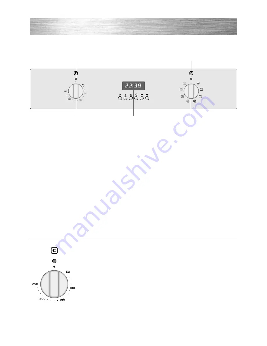
1. Oven temperature knob
2. Function selector knob
3. Power on indicator light
4. Oven temperature indicator light
5. Electronic programmer

Fig. 1.1

0

A

U

T

O

P

2

1

5

4

3

1 - CONTROL PANEL

TEMPERATURE CONTROL

The temperature range is  50°C - 250°C (MAX setting).

Fig. 1.2

Summary of Contents for CKB200

Page 1: ...Before operating this oven please read these instructions carefully BUILT IN OVEN model CKB200 Instructions for use Installation advice ...

Page 2: ...2 ...

Page 3: ...ommendations 5 Before using the oven for the first time 6 Control Panel 7 How to use the oven 8 12 Electronic Programmer 13 16 Cleaning Maintenance 17 19 Advice for the Installer 20 Installation 21 23 Electrical installation 24 25 Guarantee After Sales Service 26 ...

Page 4: ...angerous The manufacturer declines all responsibility in the event of damage caused by improper or incorrect use of the appliance IMPORTANT INFORMATION FOR CORRECT DISPOSAL OF THE PRODUCT IN ACCORDANCE WITH EC DIRECTIVE 2002 96 EC At the end of its working life the product must not be disposed of as urban waste It must be taken to a special local authority differentiated waste collection centre or...

Page 5: ...ven base or trays Remove spillages as soon as they occur Always stand back from the oven when opening the oven door to allow steam and hot air to escape before removing the food Do not hang towels dishcloths or other items on the cooker or its handle as this could be a fire hazard Make sure that electrical cords connecting other appliances in the proximity can not become entrapped in the oven door...

Page 6: ...refully before installing and using the appliance After unpacking the appliance check that it is not damaged In case of doubt do not use the appliance and contact your supplier or a qualified engineer Remove all the packing materials i e plastic bags polystyrene foam etc and do not leave it around within easy reach of children as these may cause serious injuries The packaging materials are recycla...

Page 7: ...knob 2 Function selector knob 3 Power on indicator light 4 Oven temperature indicator light 5 Electronic programmer Fig 1 1 0 A U T O P 2 1 5 4 3 1 CONTROL PANEL TEMPERATURE CONTROL The temperature range is 50 C 250 C MAX setting Fig 1 2 ...

Page 8: ...E GRILL section OPERATING PRINCIPLES Heating and cooking in the MULTI FUNCTION oven are obtained in the fol lowing ways a by normal convection The heat is produced by the upper and lower heating elements b by forced convection The circular heating element and fan constantly circulate heated air over the food in the oven for a more rapid and even cooking process It is possible to cook several dishe...

Page 9: ...ven to one of the following functions TRADITIONAL CONVECTION COOKING The upper and lower heating elements are switched on The heat is diffused by natural convection and the temperature must be set between 50 C and 250 C It is necessary to preheat the oven before introducing the foods to be cooked Recommended for For foods which require the same cooking temperature both internally and externally i ...

Page 10: ...n because the other positions have no effect The defrosting is done by simple ventilation without heat Recommended for To rapidly defrost frozen foods 1 kilogram requires about one hour The defrosting times vary according to the quantity and type of foods to be defrosted HOT AIR COOKING The circular element and the fan are on The heat is diffused by forced convection and the temperature must be re...

Page 11: ... diffused by forced convection with most of the heat being pro duced by the upper element The temperature must be set between 50 and 140 C with the temperature knob Recommended for To keep foods hot after cooking To slowly heat already cooked foods VENTILATED GRILL COOKING The infra red grill and the fan are on The heat is mainly diffused by radiation and the fan then distributes it throughout the...

Page 12: ...es of food at the same time Fish cakes and meat can be cooked together without the smells and flavours mixing The only precautions required are the following The cooking temperatures must be as close as possible with a maximum dif ference of 20 25 C between the dif ferent foods Different dishes must be placed in the oven at different times according to the cooking time required for each one This t...

Page 13: ...m for automatic oven cooking Program for semi automatic oven cooking Description of the illuminated symbols AUTO flashing Programmer in auto matic position but not pro grammed AUTO illuminated Programmer in automatic position with program set Automatic cooking taking place Timer in operation and AUTO flashing Program error The time of day lies between the calculated cooking start and end time NOTE...

Page 14: ...g 3 4 Once set the time will appear on the panel and the symbol will be lit The countdown will start immediately and may be seen at any time on the panel by simply pressing the button At the end of the time the symbol will disappear and the buzzer will sound continuously for approximately 7 min utes or until a button is pressed not the buttons After a short time the display will revert back to the...

Page 15: ...ing cycle has been superimposed on the clock In this case change the end of cooking time or the cooking period itself by follow ing the instructions above 3 Set the temperature and the cooking program by using the function selector switch and temperature knobs of the oven see specific chapters Once the oven is programmed it will switch on automatically at the right time to stop the cooking at the ...

Page 16: ...lector switch and temperature knobs see rele vant chapters The oven switches on and switches off automatically at the end of the desired cooking time During cooking the symbol remains lit and by pressing the button you can see the remaining cooking time The cooking program can be can celled at any time by pushing the button At the end of the cooking period the symbol will disappear AUTO will flash...

Page 17: ...l soap ENAMELLED PARTS All the enamelled parts must be cleaned with a sponge and soapy water only or other non abrasive products Dry preferably with a chamois leather STAINLESS STEEL SURFACES WITH ANTI FINGERPRINT TREATMENT CAUTION The stainless steel surfaces used in some ovens are protected with a Special Lacquer to reduce finger print marks To avoid damaging this lacquer do not clean the stainl...

Page 18: ...G THE OVEN LIGHT Before any maintenance is started involving electrical parts of the appliance it must be disconnected from the power supply Let the oven cavity and the heating elements cool down Switch off the electrical supply Unscrew the protective cover fig 4 3 Unscrew and replace the bulb with a new one suitable for high temperatures 300 C having the following specifica tions 230 240V 50 Hz 1...

Page 19: ...t and right hinges fig 4 4b Hold the door as shown in fig 4 4 Gently close the door fig 4 4 until left and right hinge levers A are hooked to part B of the door fig 4 4b Withdraw the hinge hooks from their location following arrow C fig 4 4d Rest the door on a soft surface To replace the door repeat the above steps in reverse order Fig 4 4d Fig 4 4c Fig 4 4b Fig 4 4a ...

Page 20: ... with the local safety standards Failure to observe this rule will invalidate the warranty Always unplug the appliance before carrying out any maintenance operations or repairs Advice for the installer The walls surrounding the oven must be made of heat resistant material Take care NOT to lift the oven by the door handle ...

Page 21: ...liance must be installed in compliance with regulations in force The oven can be fitted in standard units width and depth 60 cm Installation requires a compartment as illustrated in figures 5 1 and 5 2 On the lower side the oven must lay on supports standing the oven weight Using 4 screws not supplied the oven can be secured to the oven housing 5 INSTALLATION ...

Page 22: ...22 To ensure internal ventilation aeration channels must be provided as illustrated in the fig ures 5 3 and 5 4 Fig 5 3 30 mm 600 50 mm 50 550 Fig 5 4 ...

Page 23: ...correct opening of the oven door To ensure the trim is not damaged due to the appliance being placed on the floor the appliance should be suitably supported as in above illustrations After installation the appliance door should be slowly opened to ensure no damage has occurred No responsibility for lower trim damage will be accepted if these instructions have not been followed Fig 5 5 ...

Page 24: ... There is a danger of electric shock if the cut off plug is inserted into any 13 amp socket outlet How to wire a 13 amp plug E L N GREEN AND YELLOW Earth BROWN Live BLUE Neutral Cord clamp FUSE 13 amps Fig 6 1 Fig 6 2 FUSE DOUBLE POLE SWITCHED FUSED SPUR OUTLET ON ELECTRICAL CONNECTION For your safety please read the following information Warning This appliance must be earthed CONNECTION USING FIX...

Page 25: ... as follows The green and yellow wire must be connected to the terminal in the plug which is marked with the letter E or with the earth symbol or coloured green and yellow The blue wire must be connected to the terminal marked N or coloured black The brown wire must be connected to the terminal marked L or coloured red Note If the supply cord is damaged it must be replaced by a special cord by a q...

Page 26: ... is not second hand it has not been used commercially you have not fitted a plug incorrectly and you supply your receipt to show when you brought it The appliance has been installed as per the instructions contained within this booklet This guarantee does not affect your statutory rights GUARANTEE AFTER SALES SERVICE If you require After Sales Service contact the MASTERCARE Domestic Appliance Help...

Page 27: ...et are given as simply indicative The manufacturer reserves the right considering the characteristics of the models described here at any time and without notice to make eventual necessary modifications for their construction or for commercial needs ...

Page 28: ...code 1102419 ß5 Part Number 56324 1 ...

Reviews: