Service and Installation Manual
13
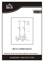
WIRING DIAGRAM
MODEL:
KCHPT60.9
MODEL:
KCHPT70.12
M
M
L
N
THERMOSTAT DISPLAY
PLUG
CIRCUITALION
FAN MOTOR
OVERLOAD
PROTECTOR
COMPRESSOR
ROOM
EVAP
SENSOR
DOOR FRAME HEATER
MIDDLE FRAME HEATER
CONDENSER
FAN MOTOR
STARTING
CAPACITOR
CURRENT
RELAY
M
M
L
N
PLUG
CIRCUITALION
FAN MOTOR
ROOM
EVAP
SENSOR
DOOR FRAME HEATER
MIDDLE FRAME HEATER
MIDDLE FRAME HEATER
CONDENSER
FAN MOTOR
STARTING
CAPACITOR
OVERLOAD
PROTECTOR
COMPRESSOR
CURRENT
RELAY
THERMOSTAT DISPLAY
Summary of Contents for KCHMT29.12
Page 17: ...Service and Installation Manual 17 WIRING DIAGRAM MODEL KCHUC27R KCHUCWT27R KCHUC27 2DR ...
Page 19: ...Service and Installation Manual 19 WIRING DIAGRAM MODEL KCHUC72R KCHUCWT72R ...
Page 20: ...Service and Installation Manual 20 WIRING DIAGRAM MODEL KCHST27 8 KCHMT29 12 KCHMT29 12 2D ...
Page 22: ...Service and Installation Manual 22 WIRING DIAGRAM MODEL KCHST70 18 KCHMT70 30 ...
Page 23: ...Service and Installation Manual 23 WIRING DIAGRAM MODEL KCHPT50 6 ...
Page 24: ...Service and Installation Manual 24 WIRING DIAGRAM MODEL KCHPT60 9 ...
Page 25: ...Service and Installation Manual 25 WIRING DIAGRAM MODEL KCHPT70 12 ...
Page 26: ...Service and Installation Manual 26 WIRING DIAGRAM MODEL KCHUC27F KCHUCWT27F ...
Page 27: ...Service and Installation Manual 27 WIRING DIAGRAM MODEL KCHUC48F KCHUCWT48F ...