Kelly Manufacturing RCA 2600-3P Installation And Operation Manual Download Page 9

RCA2600-P Series Installation/Operation Guide

Page 7 of 11

Rev 

A

KELLY MANUFACTURING COMPANY

KMC

KMC

 Publication No.1401-2

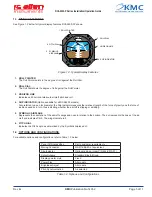
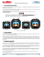
Figure 3.1, Pitch Sync

SECTION 3, OPERATION GUIDE

3.1  PRE-FLIGHT PROCEDURES

During pre-flight procedures, the instrument must be provided with adequate electrical power under normal vibration conditions 

(engine running). A red “X” appears across the screen indicating that the instrument is booting up. When the X disappears, the 

instrument is ready. The startup process should be completed within three minutes. 

NOTE

On tail-dragger aircraft, the indicator will not show as level until after achieving level flight. No adjustment are 

necessary when level flight is achieved.

3.2  IN-FLIGHT PROCEDURES - PITCH  SYNC


(Selected models only)

If you typically fly in a “nose down” or “nose up” pitch attitude, you can adjust the Airplane Symbol to match the Horizon Line on your 

instrument. The Pitch Synchronization (Pitch Sync) feature allows you to instantly sync the Airplane Symbol to the Horizon.

NOTE 

This feature is not necessary for most aircraft and is to be used only in situations where normal flight pitch is 

deviated from 0 degrees. 

PITCH SYNC ACTIVATION

Once you have achieved the desired flying pitch, activate the Pitch Sync feature by pressing 

BOTH

 PUSH BUTTONS simultaneously. 

This synchronizes the Airplane Symbol to the Horizon Line. 

The Sync ‘On’ indicator will display “SYNC” when the Pitch Sync is activated (see figure 3.1).

PITCH SYNC DE-ACTIVATION

To return to True Pitch, press 

BOTH

 PUSH BUTTONS simultaneously. This moves the Airplane Symbol back to True Pitch Indica-

tion and the Sync ‘On’ indicator will disappear.

EXAMPLE

In the example shown in Figure 3.1, The aircraft is flying level at a 10 degree nose down pitch with the Pitch Sync on. The Sync 

‘On’ Indicator is being displayed. The True Pitch Horizon is indicated by the bottom Tick Mark on the Roll Dial which is aligned with 

the 10 degree mark on the Pitch Dial. The Airplane Symbol is shown aligned with the Horizon Line at 0 degrees on the Pitch Dial.

20

10

30

10

40

10
20

10

40

30

DIM

DIM

PITCH SYNC

PUSH

BUTTONS

PUSH

BUTTONS

SYNC PITCH  

INDICATION

 TRUE PITCH 

INDICATION

SYNC PITCH 

INDICATION

 TRUE PITCH  

INDICATION

 SYNC 'ON'

INDICATOR

 SYNC 'ON'

INDICATOR

RCA 2600-2P

RCA 2600-3P

Summary of Contents for RCA 2600-3P

Page 1: ...ON OPERATION GUIDE RCA 2600 3P 3 inch P N 102 0203 04 10 P N 102 0203 04 11 RCA 2600 2P 2 inch P N 102 0202 04 10 P N 102 0202 04 11 Rev A 09 10 2015 DIM 10 10 20 20 30 10 10 20 20 30 DIM PITCH SYNC RCA 2600 3P G 3 inch P N 102 0203 04 12 P N 102 0203 04 13 RCA 2600 2P G 2 inch P N 102 0202 04 12 P N 102 0202 04 13 DIM 10 10 20 20 30 DIM 10 10 20 20 30 WITH PITCH SYNC WITHOUT PITCH SYNC KMC PUBLIC...

Page 2: ......

Page 3: ...ures Pitch Sync 7 3 3 In Flight Procedures Dimmer 8 3 4 Flight Limitations 8 3 5 Emergency Procedures 8 SECTION 4 GENERAL INFORMATION 9 4 1 Instrument Care 9 4 2 Optional Inclinometer 9 4 3 Frequently Asked Questions FAQs 10 APPENDIX A DOD 160F ENVIRONMENTAL QUALIFICATION FORM 11 LIST OF ILLUSTRATIONS Figure 1 1 General Dimensions P Models 3 Figure 1 2 General Dimensions P G Models 4 Figure 1 3 Ty...

Page 4: ...ic airplane dot is above the horizon line more blue background the aircraft is nose up If the symbolic airplane dot is below the horizon line more brown background the aircraft is nose down When the dot and wings are on the horizon line you are in level flight If the lines representing the wings roll to the left or the right the aircraft is probably starting a turn The actual bank angle is calibra...

Page 5: ...CES Ø 0 170 THRU 4 PLACES DIM 10 10 20 20 30 10 10 20 20 30 10 10 20 20 30 10 10 20 20 30 NOTE All dimensions in inches Mounting Hardware both units 6 32 screw 0 5 plus panel thickness Mating Connector both units MS3116E8 4S or equivalent PANEL CUTOUT REAR MOUNTING PANEL CUTOUT REAR MOUNTING RCA2600 3P RCA2600 2P A B D C GROUND 9 32 VDC SPARE SPARE A B D C GROUND 9 32 VDC SPARE SPARE DIM PITCH SYN...

Page 6: ...ROUND 9 32 VDC SPARE SPARE STATIC PORT 1 8 NPT PITOT PORT 1 8 NPT A B C D A B D C GROUND 9 32 VDC SPARE SPARE STATIC PORT 1 8 NPT PITOT PORT 1 8 NPT 10 10 20 20 30 DIM DIM 10 10 20 20 30 DIM 10 10 20 20 30 10 10 20 20 30 NOTE All dimensions in inches Mounting Hardware both units 6 32 screw 0 5 plus panel thickness Mating Connector both units MS3116E8 4S or equivalent PANEL CUTOUT REAR MOUNTING PAN...

Page 7: ...ents the orientation of the aircraft s wings and nose in relation to the horizon The dot represents the nose of the air craft and indicates Pitch The wings indicate roll 6 PITCH DIAL Indicates the Pitch angle as determined by the Symbolic Airplane dot 1 4 OPTIONS AND CONFIGURATIONS For available options and configurations refer to Table 1 2 below Panel Tilt Angle setting Set to customer requiremen...

Page 8: ... instrument Most mal functioning instruments can be repaired and returned to service Contact Kelly Manufacturing Company for repair and warranty information 2 3 PRE INSTALLATION INSPECTION 1 When the instrument is first received inspect container for any shipping damage 2 Carefully remove the instrument from shipping container and retain container for later storage or shipping 3 Inspect the instru...

Page 9: ... necessary for most aircraft and is to be used only in situations where normal flight pitch is deviated from 0 degrees PITCH SYNC ACTIVATION Once you have achieved the desired flying pitch activate the Pitch Sync feature by pressing BOTH PUSH BUTTONS simultaneously This synchronizes the Airplane Symbol to the Horizon Line The Sync On indicator will display SYNC when the Pitch Sync is activated see...

Page 10: ...unt of voltage the instrument is receiving At 8 5 volts a red X will appear across the screen indicating that the instrument reading is unreliable It is recommended that you install the Kelly Manufacturing ESP 1 Emergency Standby Power backup battery unit This will ensure that your instrument will have power in the event of Aircraft power failure Contact your R C Allen Kelly Mfg distributor for ad...

Page 11: ...s and wood chips that will scratch the screen Do Not use acetone or cleaners containing ammonia By avoiding all screen contact and by using proper cleaning methods the user will be rewarded with many years of service 4 2 OPTIONAL SLIP INDICATOR An optional Slip Skid Indicator inclinometer is available for all versions of the RCA2600 P The instrument can be purchased with the slip indicator attache...

Page 12: ...The tilt angle is any deviation from vertical of your instrument panel in level flight Your instrument needs to be calibrated to compensate for this angle My instrument is showing a turn in level flight what can I do It is very important to have the instrument level left and right in your panel If the instrument is not level it will show a turn when in level flight To level the instrument refer to...

Page 13: ...ory X no test performed Fungus 13 0 Equipment identified as category X no test performed Salt Fog Test 14 0 Equipment identified as category X no test performed Magnetic Effect 15 0 Equipment tested to Category Z Power Input 16 0 Equipment tested to Category BRX Voltage Spike 17 0 Equipment tested to Category A Audio Frequency Susceptibility 18 0 Equipment tested to Category Z Induced Signal Susce...

Reviews: