5/2004 Manual for connection and operation of the EV-94 EB page 1 of 28
Manual for connection and operation of
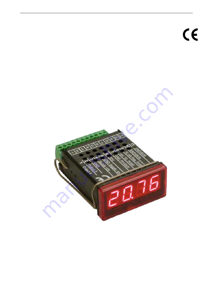
EV-94 EB
Version 2.0
KELLER AG für Druckmesstechnik
St. Gallerstr. 119
CH-8404 Winterthur
www.kellerdruck.com
Page 1: ...nual for connection and operation of the EV 94 EB page 1 of 28 Manual for connection and operation of EV 94 EB Version 2 0 KELLER AG f r Druckmesstechnik St Gallerstr 119 CH 8404 Winterthur www keller...
Page 2: ...ND 9 3 3 2 Connection with configured high side switching output PNP output switching to Uv 9 3 4 3 Connection with configured push pull switching output 10 3 5 Commen wiring of several GIA20EB 10 4 C...
Page 3: ...ce must be switched off and must be marked against using again in case of obvious malfunc tions of the device which are e g visible damage no prescripted working of the device storing the device under...
Page 4: ...ne EASYBUS interface for communicating with a host computer that makes the device to a full functions EASYBUS module When leaving our factory the EV 94 EB has been subjected to various inspection test...
Page 5: ...ge 4 and 5 9 V 28 V 0 V 30 V NPN 30V I 1A Not short circuit pro tected Switching output 1 and 2 PNP 1 and 3 2 and 3 I 200mA Not short circuit pro tected Input mA 0 mA 20 mA 0 mA 30 mA Input 0 1 2 V Fr...
Page 6: ...individual transmitter supply without individual transmitter supply Note Sig and Uv of the Transmitter must be the same potential _ Supply 9 28 VDC 4 20mA Transmitter Uv Uv _ Supply for Transmitter 4...
Page 7: ...reated like an active signal and you have to configure the de vice as TTL Hint when connecting the device You have to take care not to exceed the limits of the input voltage respective the input curre...
Page 8: ...counter When connecting contact 8 with GND e g contact 7 the counter will be reset You can do this manually e g with the help of a push button or automatically with one switching output of the device...
Page 9: ...voltage and of the maximum current of the switching outputs not even for a short period of time Please take extreme care when switching inductive loads like coils or relays etc because of their high...
Page 10: ...sure to observe the following points When several EV 94 EB s are connected to the same power supply unit it is highly recommended to isolate the sensors measuring transducers etc When the sensors mea...
Page 11: ...displays InP INPUT Use button 2 or button 3 middle resp right button to select the input sig nal see table below Validate the selection with button 1 the left button The display will show InP again De...
Page 12: ...ould display when a 0mA 4mA resp 0V input signal is attached Validate the selected value by pressing button 1 The display shows di Lo again Press button 1 again the display will show di Hi Display Hig...
Page 13: ...essing button 1 the display shows SEnS Use button 2 or button 3 middle resp right button to select your desired input signal Display Input signal RTD Notes Pt0 1 Pt100 3 wire Meas range 50 0 200 0 C 5...
Page 14: ...al circuitry you have to select TTL as your desired input signal Validate your selected input signal by pressing button 1 The display shows SEnS again When pressing button 1 again the display will sho...
Page 15: ...e your selection The display shows FiLt again Now your device is adjusted to your signal source The only thing you left do is to adjust the outputs of the device When pressing button 1 again the displ...
Page 16: ...ter starts counting upwards from 0 according to its settings The downwards counter starts counting downwards from the upper value that had been selected Feature The current value of the counter can be...
Page 17: ...g the measurement With a pre scaling factor of 100 se lected you will get 18 pulses per litre With a maximum flow rate of 300 litres you will be getting a pulse count of 18 300 5400 Press button 1 to...
Page 18: ...s to display InP When pressing button 1 again the device will display Adr address Use button 2 and button 3 to select the desired address 0 239 of the device Press button 1 to validate the selected de...
Page 19: ...ready made for output 1 2 dEL delay of output 2 2 out kind of output 2 2 Err preferred state of output 2 When pressing button 1 again only if you configured the device with min max alarm the device wi...
Page 20: ...2 point controller with min max alarm digital 2 point controller min max alarm 2P AL 5 2 min max alarm common min max alarm AL F1 5 3 min max alarm individ ual max alarm min alarm AL F2 5 3 5 1 2 poin...
Page 21: ...1 off When the temperature rises above 20 C the device turns its output 1 on when falling below 22 C the device will turn its output 1 off Note Depending on the inertia of your cooling circuit an ove...
Page 22: ...tton 1 again the device will be displaying A dEL delay of the alarm function Use button 2 and button 3 to set the desired delay of the alarm function Note The unit of the value to be set is in sec The...
Page 23: ...FFS again When pressing button 1 again the device will be displaying SCAL scale slope Use button 2 and button 3 to select the desired slope adjustment The slope adjustment will be entered in The value...
Page 24: ...PC e g EBW1 EBW64 EB2000MC Software for communication with the device EBS9M 9 channel software for displaying a measured value EASYCONTROL multi channel software for real time recording and displayin...
Page 25: ...low and should be increased Err 7 System error The device features an integrated self diagnostic function which checks essential parts of the de vice permanently When detecting a failure error messag...
Page 26: ...0 200 0 C resp 58 0 392 0 F 0 1 C resp F 3 wire connection max perm line resistance 20 Ohm Pt100 1 C 200 850 C resp 328 1562 F 1 C resp F 3 wire connection max perm line resistance 20 Ohm RTD probes...
Page 27: ...4 Hz Output functions 2 point 3 point 2 point with alarm min max alarm common or individual Switching points arbitrary Display approx 10 mm height 4 digit red LED display Handling 3 push buttons acces...
Page 28: ...di Hi Acknowledge high input value Press button 1 Li Measuring range limit Limit button 2 or 3 off on Er on rG Select measuring range limit off button 1 Li Acknowledge measuring range limit button 1...