Kele KCO-NO2 Preliminary User'S Manual Download Page 4

Kele    KCO-NO2  User’s  Manual 

Last Rev: 6/15/2020 

Kele • 3300 Brother Blvd. • Memphis, TN  38133

 • 

WWW.KELE.COM


Page 4 of 14 


PRELIMINARY 

M

ECHANICAL 

I

NSTALLATION


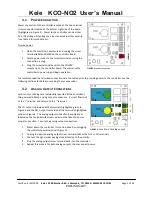
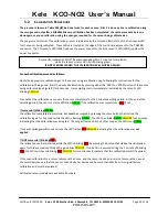
The Model KCO-NO2 is available in two versions of a gray, powder-coated, 18 Gauge steel enclosure.  The 
removable, lockable, hinged-cover version is shown in Figure 1 and the screw-down cover version is shown in 
Figure 2.  All electronics are attached to the front cover.  There are ½” conduit knock-outs on all sides for electrical 
connections.  In potentially damp locations the knock-out on the bottom of the case should be used to minimize 
the possibility of water entry.  

DO NOT USE THE VENT HOLES FOR WIRE ENTRY.


This unit is designed to mount to a rigid, vibration-free surface near the middle of the area to be monitored about 
5 feet above the floor.  It should be located where there is free airflow - avoid corners or recesses.  The air vents 
on the sides of the enclosure should not be closer than 1 foot from the nearest perpendicular wall and must not be 
obstructed or painted-over. 

E

LECTRICAL 

I

NSTALLATION


The controller is not equipped with a power switch;  it is operational whenever sufficient power is applied to the 
power input terminals.   

All electrical connections to the controller are made through screw terminals that can be unplugged during wiring.  
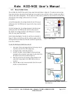
The controller’s enclosure contains multiple conduit knockouts for flexibility during installation; refer to Figure 1 
and Figure 2 for details and dimensions of the enclosures. 


FIGURE 1: 

CO/NO

2

 HINGED FRONT PANEL ENCLOSURE DIMENSIONS


FIGURE 2: 

CO/NO

2

 SCREW FRONT PANEL ENCLOSURE DIMENSIONS


Summary of Contents for KCO-NO2

Page 1: ...PRELIMINARY Kele KCO NO2 PRELIMINARY User s Manual...

Page 2: ...elay Connections 6 4 Operational Description 7 4 1 Startup 8 4 2 Setting Warning and Alarm Thresholds 8 4 3 Warning and Alarm Conditions 8 4 4 Sensor Readings 8 5 Sensor Calibration 9 5 1 Calibration...

Page 3: ...DT relays for warning and alarm outputs 10 Amps max at 120 VAC RMS or 30 VDC Concentration Reporting Outputs Powered 4 20 mA current loop output for each sensor 4 mA output 0 ppm concentration 20 mA f...

Page 4: ...id vibration free surface near the middle of the area to be monitored about 5 feet above the floor It should be located where there is free airflow avoid corners or recesses The air vents on the sides...

Page 5: ...controller see the following sections for details on making these connections 3 2 ANALOG OUTPUT CONNECTIONS Each sensor s readings are individually reported at the controller s two powered 4 20mA ana...

Page 6: ...while the relay output is deactivated the voltage attached to the NC terminal is removed when the relay output is activated An example wiring diagram for relay connections are provided in Figure 6 Whe...

Page 7: ...ensor modules are field replaceable each sensor module can be replaced with minimal effort when it reaches end of life EOL while leaving the main control mounted and wired refer to Section 7 1 The con...

Page 8: ...can be adjusted for each sensor via dip switches on the controller s main board shown in Figure 7 Refer to details on setting the thresholds for each sensor in Table 8 NO2 CO Federal OSHA Personal Exp...

Page 9: ...or must be sequentially calibrated with two different gases The Zero gas is the same for both sensors and is used for the zero calibration which must be done first The span gas is different for each s...

Page 10: ...e sampling period At the end of the sampling period the sensor s status LED blinks GREEN if the calibration was successful or RED if not If successful blinking GREEN the calibration completed successf...

Page 11: ...KCO NO2 User s Manual Last Rev 6 15 2020 Kele 3300 Brother Blvd Memphis TN 38133 WWW KELE COM Page 11 of 14 PRELIMINARY FIGURE 9 GAS calibration Procedure done with zero gas then span gas for each se...

Page 12: ...LD REPLACEMENT OF SENSOR MODULES Sensor modules must be replaced when they reach their End of Life Care should be taken to ensure the correct sensor modules are placed in the proper location CO is on...

Page 13: ...and for ensuring that any product into which Products are incorporated other components used with DCS Products and the purposes for which DCS Products are used are appropriate and compatible with tho...

Page 14: ...peration both sensors are regularly tested to detect common failures If a failure is detected the front panel status LED for that sensor will blink red and its concentration reporting analog output wi...

Reviews: