


Kele KCO-NO2 User’s Manual
Last Rev: 6/15/2020
Kele • 3300 Brother Blvd. • Memphis, TN 38133
•
WWW.KELE.COM
Page 3 of 14
PRELIMINARY
1
S
PECIFICATIONS
Mechanical
Chassis Construction
18 Ga. Grey powder-coated steel. Lockable, hinged or screw-on
cover style available.
Weight
2.0 Lbs
Operating Temperature
-20 to 50°C
Operating Humidity
15 – 90 %RH
Storage Temperature
0 to 20°C (to minimize sensor degradation)
Case Dimensions (H x W x D)
6.4” x 5.9” x 2.4” (163.5 x 150.8 x 60.7 mm)
Sensor Housing Diameter
20.4 mm (.8032 “ approx. 13/16”)
Recommended calibration cap diameter
20.5 mm (.807”)
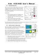
External Indicators
Separate tri-color LEDs indicate operational status of each senor.
TABLE 1: MECHANICAL SPECIFICATIONS
Electrical
Operating Power Voltage
13 to 30 VAC (RMS) or 15 to 45 VDC
Power Consumption
< 5W
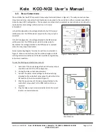
Control Relays
Separate SPDT relays for warning and alarm outputs.
10 Amps max at 120 VAC (RMS) or 30 VDC.
Concentration Reporting Outputs
Powered 4 – 20 mA current loop output for each sensor.
4 mA output => 0 ppm concentration. 20 mA => full scale output.
Maximum loop resistance: 510Ω
TABLE 2: ELECTRICAL SPECIFICATIONS
Carbon Monoxide Sensor (CO)
Sensor Type
Electrochemical
Measurement Range
0 – 100 ppm
Analog Output Range
4mA to 20mA (corresponds to 0 to 100 ppm)
Accuracy
±5% of Full Scale (typical)
Calibration Interval
6 Months
Sensor Life
2 Year typical
1
Calibrated Field-Replaceable Sensor
YES
TABLE 3: CO SENSOR SPECIFICATIONS
Nitrogen Dioxide (NO
2
)
Sensor Type
Electrochemical
Measurement Range
0 –10 ppm
Maximum Permissible Exposure
150 ppm
Analog Output Range
4mA to 20mA (corresponds to 0 to 10ppm)
Accuracy
± 1.5 ppm (typical)
Calibration Interval
6 Months
Sensor Life
2 Year typical
Calibrated Field-Replaceable Sensor
YES
TABLE 4: NO
2
SENSOR SPECIFICATIONS
1
Exposure to harsh ambient environmental conditions may shorten senor life.


