background image

Maintenance

The F60 is a low maintenance device.  If it is correctly installed in a location 

that is out of direct exposure to the elements it should give a long and 

reliable life and require no maintenance at all.  

Factors that may reduce its life are lightning strikes or power surges, failure 

to fully tighten its lid and cable glands, exposure to pressures or temperatures 

in excess of its ratings and operation outside its electrical limitations in 

terms of supply voltage and motor loads.

Spare Parts

Spare paddles are available for the F60 pump controller from your supplier.

Warranty

The F60 is warranted against faulty workmanship and materials for a period 

of 12  months from the date of purchase. Our complete warranty statement 

can be downloaded from : 

http://www.kelco.com.au/menu/information/warranty-statement

If a warranty issue arises with this product contact your supplier or Kelco 

Engineering Pty Ltd.  You will be issued with a returns goods authorisation 

number.  The RGA number and proof of purchase must accompany any 

goods returned to us under warranty.

31

Summary of Contents for F60

Page 1: ...KELCO F60 DIGITAL PUMP CONTROLLER INSTALLATION INSTRUCTIONS KELCO Engineering Pty Ltd Sydney Australia www kelco com au Version 180516...

Page 2: ...e the pump will continue to run for a short period held on by the controller s built in run on timer If acceptable conditions fail to return the pump will be shut down after the run on time period Pre...

Page 3: ...mbly Onto The Paddle Assembly 9 Trimming the Paddle 10 Detaching the Electrical Housing 11 Sensitivity Adjustment 12 Limitations 13 Table of Limitations 14 Electrical 15 The HD Heavy Duty Terminal 16...

Page 4: ...instructions in the literature accompanying the pump controller WARNING This symbol is intended to alert the user to the presence of un insulated dangerous voltage within the pump controller s enclos...

Page 5: ...t Do not drill holes in this controller s casing Refer all installation and servicing to qualified service personnel Servicing is required when the controller has been damaged in any way such as expos...

Page 6: ...ller s simple programmable interface This document sets out in detail the installation and functions of the controller and some of the main ways in which it can be used in pumping and irrigation syste...

Page 7: ...d in the discharge pipework of the pumping system either before or after the system s air cell If the system does include an air cell a decision has to be made as to which side of the air cell to loca...

Page 8: ...he slow pressure fall from the air cell After The Air Cell If you install the F60 in the pipework after the air cell the controller will start the pump each time flow pushes its paddle forward or each...

Page 9: ...controller for extended periods Without its lid in place the F60 is not water resistant and presents a potential shock hazard Take great care not to splash water onto the controller when the lid is n...

Page 10: ...m Allen Key supplied Tighten the screw and then release your hand from the top of the housing Pressing down with your hand on the housing preloads the O ring seal between the housing and the paddle as...

Page 11: ...ALIGNING THE PADDLE ASSEMBLY 8...

Page 12: ...Locking the electrical housing onto the paddle assembly LOCKING SCREW USE 3mm A F ALLEN KEY PROVIDED TO LOCK THIS SCREW SECURELY CONTROLLER HOUSING PADDLE ASSEMBLY PADDLE PIVOT BOLT 9...

Page 13: ...lows you to enter your pipe diameter and paddle dimensions It will then determine if the selected paddle dimensions are adequate for the application Spare paddles to suit the F60 pump controller are a...

Page 14: ...the paddle housing Simply reverse this procedure to refit the electrical housing to the controller taking care to ensure the pressure seal O ring on the top of the wet end is in place and is clean an...

Page 15: ...ind the sensitivity adjustment screw anti clockwise outward the force against the paddle that resists flow will be reduced The paddle will become increasingly more sensitive and will respond to progre...

Page 16: ...e life from the controller we recommend it be protected from direct exposure to the sun and rain Intense sun light will eventually cause discoloration of the clear lid on the controller and will also...

Page 17: ...minutes in 1 minute increments Anti Cycling Modes 1 to 3 Only Adjustable from 1 motor start per hour to 1800 starts per hour Run Dry Auto Restart User Settable to Single or Repeated Attempts Adjustabl...

Page 18: ...so be operated from an 18 to 24V AC or DC supply by utilising the low voltage active terminal LV and common neutral terminal N see the included wiring diagrams When operated from a low voltage DC supp...

Page 19: ...d when the F60 pump controller is connected to external timers low wattage relays or to any other external device where voltage free contacts are required It is strictly intended for the direct contro...

Page 20: ...rom 7 to 9mm diameter See attached sketch for assembling the cable gland components The controller is supplied with a set of steel crimp rings The crimp rings are to provide strain relief for the cont...

Page 21: ...nal chamfer faces toward the rubber groumet Controller Housing CABLE GLAND ASSEMBLY Crimp the ears of the strain relief ring onto cable and pull cable back into slots in the gland housing NOTE As supp...

Page 22: ...at 30VDC Resistive Load 500mA at 5VDC Minimum Load RELAY 2 CONTACT RATING 16A at 250VAC Resistive Load 16A at 30VDC Resistive Load Do not connect any supply greater than 25VAC or DC to the LV termina...

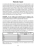
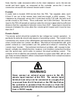
Page 23: ...n must be regarded as operating at full mains potential whenever the F60 is powered from the mains The remote switch can be installed some distance from the F60 The maximum distance is limited by cabl...

Page 24: ...ts should only require a low wetting current The current in the remote loop only runs to a few milliamperes and requires a switch that will conduct when closed under low current conditions Mechanical...

Page 25: ...IT IS FAR BETTER TO HAVE A PERMANENT SUPPLY ONTO THE ACTIVE AND NEUTRAL TERMINALS AND TO CONNECT A REMOTE SWITCH TO THE LV AND R TERMINALS SUPPLY NEUTRAL SUPPLY ACTIVE EXTERNAL ALARM CONNECTIONS RELA...

Page 26: ...CONTROL OF A SINGLE PHASE PUMP MOTOR WITH A SECONDARY SOURCE BACK UP PUMP AND A REMOTE INPUT SWITCH 23 CONNECTIONS FOR PLUG AND PLAY INSTALLATION...

Page 27: ...LOW VOLTAGE AC CONNECTIONS WITH A REMOTE INPUT SWITCH LOW VOLTAGE DC CONNECTIONS WITH A REMOTE INPUT SWITCH 24...

Page 28: ...CONTROL OF A SINGLE PHASE PUMP MOTOR WITH REMOTE INPUT AND AN EXTERNAL ALARM BASIC SINGLE PHASE WIRING DIAGRAM 25 Maximum 2 4kW Maximum 2 4kW...

Page 29: ...RNAL ALARM 26 Alarm or siren 220 240 VAC device 16A maximum load resistive Coil A3 A2 A1 N Contactor 3 Phase pump motor 3 Phase supply Remote Level or Pressure Switch Note Contacts are normally open 3...

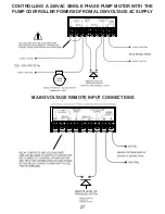
Page 30: ...CONTROLLING A 240VAC SINGLE PHASE PUMP MOTOR WITH THE PUMP CONTROLLER POWERED FROM A LOW VOLTAGE AC SUPPLY MAINS VOLTAGE REMOTE INPUT CONNECTIONS 27 Maximum 2 4kW...

Page 31: ...y voltage across the positive and negative terminals must never exceed 14VDC or the flow switch will be damaged The supply terminals are reverse polarity protected however the flow switch will simply...

Page 32: ...F60 Controls their Functions 29...

Page 33: ...erminal Link this terminal to the relay 1 normally open terminal when directly controlling pump motors 10 Remote Input Light Blue This light is on whenever the remote input switch is closed 11 Program...

Page 34: ...tations in terms of supply voltage and motor loads Spare Parts Spare paddles are available for the F60 pump controller from your supplier Warranty The F60 is warranted against faulty workmanship and m...

Page 35: ...834 844 Head Office and Factory 9 9 Powells Road Brookvale 2100 Australia Postal Address PO Box 7485 Warringah Mall NSW 2100 Phone 61 2 99056425 Fax 61 2 99056420 Email sales kelco com au Web www kelc...

Page 36: ...e the pump will continue to run for a short period held on by the controller s built in run on timer If acceptable conditions fail to return the pump will be shut down after the run on time period Pre...

Reviews: