9
WALL MOUNTING THE E30
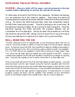
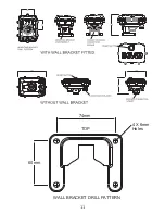
The E30 pressure switch is supplied with a wall mounting bracket that can be
used to mount the pressure switch in locations away from the pressure tapping
point. To bracket mount the E30,
fi
rst install the bracket by drilling a hole pattern.
Secure the bracket to the wall or mounting using suitable screws (not supplied).
Fit a 1/4” BSP elbow (not supplied) to the E30’s process port using Te
fl
on tape.
The elbow should point squarely toward the cable glands on the E30. Install a
suitable tube adaptor into the elbow to facilitate connection to a length of capillary
tube. Typically, the capillary tube to use for this will be 6 to 8mm diameter.
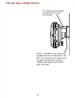
Wire up the electrical head of the E30 and fully tighten all cable glands. Lock the
electrical head onto the wall bracket using the red bolt supplied with the E30.
Note that there are two ears on the wall bracket that engage in two notches on the
under side of the E30’s electrical housing. Using a suitable tube adaptor terminate
the capillary tube at the pipe system’s tapping point. If water hammer or violent
pressure surges are likely, coil the capillary tube between its two termination
points so the added length of the capillary tube acts as a shock absorber.
DETACHING THE ELECTRICAL HOUSING
WARNING:
Always switch off the power and de-pressurise the pipe
system before attempting to remove the electrical housing.
To allow easy removal of the E30 from the pipework, the electrical housing
can be detached from the process adaptor. Removing the electrical
housing allows access to the process adaptor without the need to disconnect
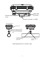
wiring. To remove the electrical assembly undo and completely remove
the M4 Allen head locking screw. Once the locking screw is removed, lift
the electrical housing straight off, do not twist it when doing this. Once the
electrical housing has been removed, the process adaptor can be
unscrewed from the pipework. Simply reverse this procedure to re
fi
t the
electrical housing to the E30, taking care to ensure the O-ring on the top of
the process adaptor is in place and is clean and in good condition.
Summary of Contents for E30
Page 11: ...11 74mm 60mm 4 X 6mm Holes TOP WALL BRACKET DRILL PATTERN...
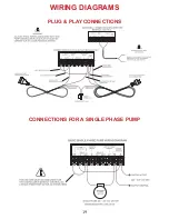
Page 19: ...19 WIRING DIAGRAMS PLUG PLAY CONNECTIONS CONNECTIONS FOR A SINGLE PHASE PUMP...
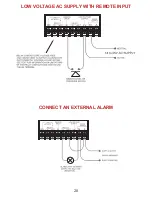
Page 20: ...20 LOW VOLTAGE AC SUPPLY WITH REMOTE INPUT CONNECT AN EXTERNAL ALARM...
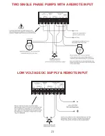
Page 21: ...21 TWO SINGLE PHASE PUMPS WITH A REMOTE INPUT LOW VOLTAGE DC SUPPLY REMOTE INPUT...


