DMM6500 6½ Digit Multimeter User's Manual
Section 9: Measuring power using digitizing and TSP-Link
DMM6500-900-01Rev. A / April 2018
9-3
3. Connect the computer to the DMM6500 that is set to node one.
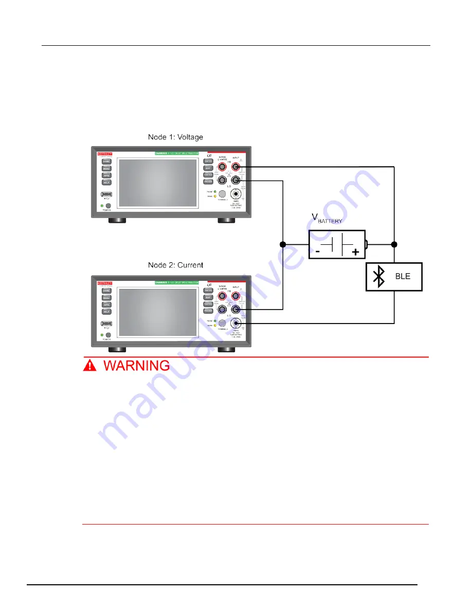
4. Connect the test leads of the instrument measuring voltage in parallel with the battery of the
device.
5. Connect the test leads of the instrument measuring current in series with the battery of the
device.
Figure 43: Two nodes measuring current and voltage
To prevent electric shock, test connections must be configured such that the user cannot
come in contact with test leads or any device under test (DUT) that is in contact with the
conductors. It is good practice to disconnect DUTs from the instrument before powering the
instrument. Safe installation requires proper shields, barriers, and grounding to prevent
contact with test leads.
There is no internal connection between protective earth (safety ground) and the LO
terminals of the DMM6500. Therefore, hazardous voltages (more than 30 V
RMS
) can appear on
LO terminals. This can occur when the instrument is operating in any mode. To prevent
hazardous voltage from appearing on the LO terminals, connect the LO terminal to protective
earth (safety ground) if your application allows it. You can connect the LO terminal to the
chassis ground terminal on the front panel or the chassis ground screw terminal on the rear
panel. Note that the front-panel terminals are isolated from the rear-panel terminals.
Therefore, if you are using the front-panel terminals, ground to the front-panel LO terminal. If
using the rear-panel terminals, ground to the rear panel LO terminal. Failure to follow these
guidelines can result in injury, death, or instrument damage. Failure to recognize and observe
normal safety precautions could result in personal injury or death.


