T-GPS User Manual Version 1.2 | 21
4.16
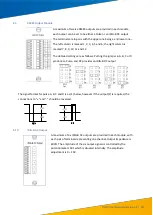
Optical Output Module
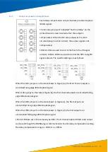
Each optical signal output I module provides 8 optical signals. Each
signal can be set to IRIG-B DC; Pulse A, B, C, D; TXD; IRIG-B
DC’
, pulse
A’
,
B’
,
C’
,
D’; a
nd
TXD’
optical signal outputs.
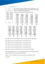
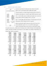
Jumpers 20S1 to 20S8 control the outputs, as follows:
When 20S1 is as shown in (a) Optical output 1 is providing an IRIG-B DC optical signal
When 20S1 is as shown in (b) Optical output 1 is controlled by Pulse A
When 20S1 is as shown in (c) Optical output 1 is controlled by Pulse B
When 20S1 is as shown in (d) Optical output 1 is controlled by Pulse C
When 20S1 is as shown in (e) Optical output 1 is controlled by Pulse D
When 20S1 is as shown in (f) Optical output 1 is providing a TXD optical signal
The remaining positions DC’, A’ –
D’ and TXD’ (20S1 (g) –
(l)) are similar, except their on/off
states are opposite to the corresponding signals above.
Outputs 2
–
8 are controlled in the same manner but by the jumpers 20S2
–
20S8
respectively.
(b)
20S1
(c)
20S1
(d)
20S1
(e)
20S1
(f)
20S1
(g)
20S1
(h)
20S1
(i)
20S1
(j)
20S1
(k)
20S1
(l)
20S1

