T-GPS User Manual Version 1.2 | 16
4.7
Serial Port Output Module II
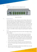
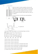
The module has up to four serial signals, each routed to a DB9 interface.
Each output can be configured as an RS-232 level or RS-422 level output.
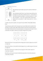
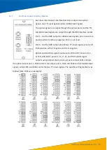
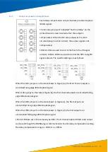
20S1 to 20S4 on the printed board are used to control the outputs of
COM1 to COM4 respectively. The specific setting methods are as follows:
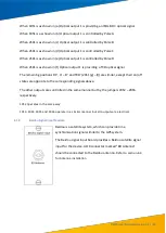
When 20S1 is in the (a) state, COM1 port outputs
“PPS2” type pulse signal.
When 20S1 is in the (b
) state, COM1 port outputs “PPS
1
” type pulse signal.
When 20S1 is in the (c
) state, COM1 port outputs “
TXD2
” type pulse signal.
When 20S1 is in the (d
) state, COM1 port outputs “
TXD1
” type pulse signal.
20S2 to 20S4 are set in the same way as 20S1.
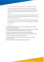
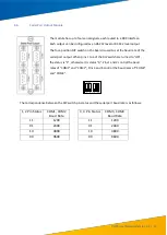
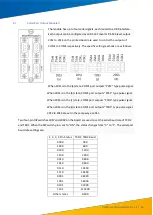
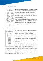
Two four-pin DIP switches 20S7 and 20S8 on the board are used to set the serial baud rate of TXD2
and TXD1. When the DIP switch pin is set to "ON", the status
changes from “0” to
"1". The serial port
baud rate settings are:
1, 2, 3, 4 Pin Status TXD1, TXD2 Baud
Rate
0000
300
1000
600
0100
1200
1100
2400
0010
4800
1010
9600
0110
14400
1110
19200
0001
38400
1001
56000
0101
57600
1101
115200
Other states
9600

