background image

INSTALLATION INSTRUCTIONS

R−410A, Two−Stage Split System Air Conditioner

12

421 01 6002 01

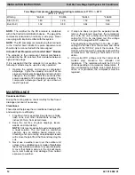
                      Two−Stage Compressor Resistance (winding resistance) at 70

°

F +/− 20

°

F

(21

°C

 +/− 11

°

C)

Winding

*4A624

*4A836

*4A648

*4A660

Start (S−C)

1.40

1.29

1.52

0.60

Run (R−C)

1.32

0.89

0.64

0.49

NOTE: The rectifier for the DC solenoid is contained
within the Comfort Alert UltraTech device.  The plug at the
compressor solenoid is an ordinary 2−wire plug.  Never
use a plug with internal rectifier with this system.

NOTE: The DC compressor solenoid plug that connects
to the Comfort Alert UltraTech is polar dependent and
should only be connected with the tabs aligned.

Unloader Test Procedure with Comfort Alert

t

 Module

The unloader is the compressor internal mechanism,
controlled by the DC solenoid, that modulates between
high and low−stage.

If it is suspected that the unloader is not working, the
following methods may be used to verify operation.

1.

Operate the system and measure compressor
amperage.  Cycle the unloader on and off at ten
plus second intervals by applying and removing Y2
voltage to the module.  Wait five seconds after
power is applied to Y2 before taking a reading.  The
compressor amperage should go up or down at
least 25 percent.

2.

If step one does not give the expected results,
remove the solenoid plug from the compressor
and, with the unit running and the thermostat
calling for Y2 to be energized, test the voltage
output at the plug with a DC voltmeter.

The reading here should be 4 to 18 volts.  If NOT,
unplug the harness from the module and check
voltage at the “DC Sol” pins of the module.  The
module will not power the unloader solenoid if the
compressor is not running or fault code 1 or 9 is
active.

3.

If the correct DC voltage is at the control circuit
molded plug, measure the unloader coil
resistance.  The resistance should be 32 to 60
ohms depending on compressor temperature.  If
the coil resistance is infinity, much lower than 32
ohms, or is grounded, the compressor must be
replaced.

MAINTENANCE

Condensate Drain

During the cooling season, check monthly for free flow of
drainage and clean if necessary.

Cleanliness

These tips will help keep the air conditioner looking better
and working more efficiently:

1.

Free flow of air is essential. Keep fences, shrubs,
trash cans, and other obstructions at least 18
inches (457mm) from all coil inlets.

2.

Keep the coil free of grass clippings, leaves,
weeds, and other debris.
NOTE: Coil may occasionally require cleaning with
a liquid solution. The coil must be cold when
cleaning. Use an alkaline based cleaner only.
Cleaning a hot coil or using an acid based cleaner
will remove the paint from the fins and may clog the
coil.

3.

Never use a weather cover over the outdoor unit
unless it is a ventilated type or made of breathable
fabric that will allow moisture to evaporate rapidly.
A cover that holds moisture in the unit will cause
more rust build−up and damage than normal
exposure to weather.

Summary of Contents for R?410A

Page 1: ...ner The signal word CAUTION is used throughout this manual in the following manner Signal Words on Product Labeling Signal words are used in combination with colors and or pictures on product labels W...

Page 2: ...or bedroom windows Noise may carry into the openings and disturb people inside Locate unit in a well drained area or support unit high enough so that water runoff will not enter the unit Locate unit...

Page 3: ...les Wall 6 152mm 24 610mm Service Wall Wall Wall 6 152mm 6 152mm Post Wall Wall 18 457mm 18 457mm 18 457mm 18 152mm 6 152mm 6 152mm 6 152mm 18 457mm 18 457mm 18 457mm 18 457mm 24 610mm Service 24 610m...

Page 4: ...ture is a home or apartment avoid locating the unit over bedrooms or study NOTE When unit is to be installed on a bonded guaranteed roof a release must be obtained from the building owner to free the...

Page 5: ...le avoiding unnecessary bends and turns Always insulate the entire suction line Both lines should be insulated when routed through an attic or when routed through an underground raceway When routing r...

Page 6: ...are plugged from the factory Outdoor units are shipped with a refrigerant charge sealed in the unit Leave the service valves closed until all other refrigerant system work is complete or the charge w...

Page 7: ...system is free of air and water Watch the vacuum gauge as the system is pulling down The response of the gauge is an indicator of the condition of the system refer to Figure 7 With no leaks in the sy...

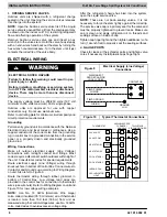
Page 8: ...mum to 253 volts maximum 60 Hz single phase Outdoor units are approved for use with copper conductors only Do not use aluminum wire Refer to unit rating plate for minimum circuit ampacity and circuit...

Page 9: ...r example a 25 foot 7 6m line set is 10 feet 3m longer than the specified 15 feet 4 6m Add 0 6 ounces 17g charge for each of the extra 10 feet 3m 10 x 0 6 6 0 ounces additional charge 3m x 17g 51g add...

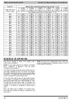
Page 10: ...42 106 41 439 118 48 116 47 114 46 112 44 110 43 108 42 450 120 49 118 48 116 47 114 46 112 44 110 43 462 122 50 120 49 118 48 116 47 114 46 112 44 474 124 51 122 50 120 49 118 48 116 47 114 46 SEQUEN...

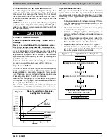
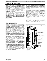
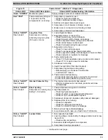
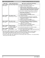
Page 11: ...d stage of the thermostat is calling for more capacity a starting advantage under low voltage conditions TROUBLESHOOTING Models are factory equipped with the Comfort Alert UltraTech Diagnostics device...

Page 12: ...for Y2 to be energized test the voltage output at the plug with a DC voltmeter The reading here should be 4 to 18 volts If NOT unplug the harness from the module and check voltage at the DC Sol pins o...

Page 13: ...age 4 Faulty metering device Check TXV bulb installation size location and contact Check if TXV is stuck closed or defective 5 Condenser coil is dirty 6 Liquid line restriction filter drier blocked 7...

Page 14: ...pply and the compressor S terminal 3 Compressor start winding is damaged Check compressor motor winding resistance Yellow ALERT Flash Code 7 Open Run Circuit Current only in start circuit 1 Open circu...

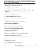
Page 15: ...HFC refrigerants is only compatible with POE oils Vacuum pumps will not remove moisture from oil Do not use liquid line filter driers with rated working pressures less than 600 psig Do not install a s...

Reviews: