background image

System Management 

48 


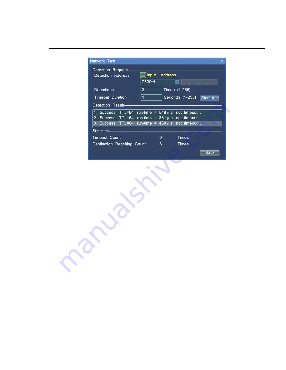
Figure 9-4 Network Test 

Detection Request: Select or enter the detection address or detection count, duration, and so on; 

Start Test: Detect the network situation according to the set detection request;   

Detection Result: The detection result will be displayed in the list;   

Statistics: displays the detection conditions, timeout count and destination reaching count. 

9.4 Dual 

screen 

NVR2860 support two display monitors at the same time. 

Click dual screen, and set single or dual output. 

When video is VGA, two displays both can be enabled as main output and secondary output, 
however main output only when HDMI. 

9.5 Image 

cut 

NVR2860 support image cut. 

Cut your image edge according your display, and the value should be divided by 4, if not, the 
system will adjust according your entering. 

Summary of Contents for KDM201S

Page 1: ...NVR User Manual ...

Page 2: ...strates functional operations of the NVR system Chapter 10 presents the operation method in case of multiple NVR Chapter 11 discusses frequently asked questions Glossary presents terminologies used in the manual Conventions Indicates special attention of users and following these descriptions or prompts will lead to better application of the NVR system Bold Indicates main features interface parame...

Page 3: ...o Icon 3 1 4 Turn on Turn off 3 1 5 User Login Logout 4 1 6 Entering Digits Characters 5 1 7 How to Get Help 6 2 Video Surveillance 7 2 1 PTZ Control 8 2 2 Snapshot 13 2 3 Voice call 13 2 4 Camera Sequence 14 2 5 Layout 15 2 6 Page Sequence 16 2 7 Layout Scheme 16 2 8 Scheme Sequence 17 3 Playing Records 19 3 1 Record Control 19 3 2 Schedule 20 3 3 Record Policy 21 3 4 Replay 22 ...

Page 4: ...IO Input 31 5 1 1 Access IO Input device 31 5 1 2 Name the alarm 32 5 1 3 Alarm Linkage Settings 32 5 2 Service Alarm 35 5 2 1 Motion detection 35 5 2 2 Name the alarm 35 5 2 3 Alarm Linkage Settings 35 5 2 4 System Alarm 35 5 3 Current Alarm 36 5 4 History Alarm 36 6 TV Wall Management 38 6 1 TV Wall Scheme 38 6 2 TV Wall Video Edit 39 6 3 TV Wall Video Sequence 39 7 User Management 41 7 1 Add a ...

Page 5: ...nagement 43 8 1 View Log 43 8 2 Delete log 44 9 System Management 45 9 1 General Settings 45 9 2 System Information 47 9 3 Network Test 47 9 4 Dual screen 48 9 5 Image cut 48 10 Operating Multiple NVR 49 10 1 Setting NVR No 49 10 2 Remote control over NVR 49 11 Question and Answer 51 12 Glossary 53 ...

Page 6: ...820 NVR2820E NVR2860 and KDM201S The NVR mentioned in this document refers to all kinds of NVR and KDM201S besides declaration specific 1 1 Operation Mode To control the NVR Remote control applicable to NVR2820 and NVR2860 USB Mouse Surveillance keyboard NVR Station Refer to the help file for details 1 1 1Remote Control Figure 1 1 Remote Control ...

Page 7: ...rn to the previous menu and press continuously to back to the video Right click to select the main menu and right click once to return to the previous menu while continuously to back to the video Press on the keyboard to open the menu and press to back to the previous while continuously to back to the video 1 3 Icons 1 3 1Toolbar Icons Press any key in the numeric area except 0 or move your mouse ...

Page 8: ...n NVR alarm input disk error Disk full No recording space NVR offline Slower network speed IP conflict Snapshot space full Voice broadcast USB device ANR No disk Click icons on the screen to show the ToolTips 1 4 Turn on Turn off Turn on After the power socket is connected press the power switch on the rear panel of NVR Turn off Press on your remote control and press again after the display off th...

Page 9: ... live video screen automatically after it turn on enter User and Password in the User Login interface to operate The valid time for user can be set in general settings see Section 9 1 for details Figure 1 2 User Login Notice Both username and password are admin by default You may modify the password in the user management interface If you forget your password please select Forget Password and cont...

Page 10: ...ard Digits Lower case letters Upper case letters Chinese characters Special symbols To Switch input method In the input status press on your remote control to switch the input method In the input status click the status icon after the input box to switch the input method Click the input box to open the soft keyboard ...

Page 11: ...f letters To enter Chinese characters The icon show Chinese input please type in full spelling method To enter special symbols In the status enter special symbols as you want Please refer to the soft keyboard for correct symbols 1 7 How to Get Help Please consult with your network administrator or refer to the NVR Administrator Guide to install or configure your NVR surveillance system Refer to th...

Page 12: ...trol Control the camera such as zoom and focus Video view Select a video source to display and press once to view the next which increases cyclically according to the camera sequence in the video source list Secondary output Auxiliary Picture TV Wall Available for NVR2860 Only one video displayed in the secondary monitor Recording Mode set the recording mode of the current camera Enable Auto Disab...

Page 13: ...eset sequence scheme or edit the sequence scheme Scheme sequence Edit sequence scheme and enable disable the scheme Network test Test the network conditions of the current camera Refer to Section 9 3 Network Test for details Current alarm View the current alarm 2 1 PTZ Control PTZ control method After choosing a video live select on the toolbar shortcut key 2 or the video live menu to enter the PT...

Page 14: ...rtcut key 6 decrease shortcut key 4 Focus adjustment increase focal length shortcut key 9 decrease focal length shortcut key 7 Auto focus shortcut key 8 Fast PTZ Select the video and click the icon on the top of the video then click direction arrows on the video Operate on the video directly down and up and right and left and press the center icon to reset ...

Page 15: ...r set image display mode here Control Amplitude The size of control amplitude indicates the PTZ control amplitude that is the size of remote control step The greater the amplitude is the larger the remote control stepping amplitude will be or vice versa Preset Position sets the current PTZ status to a preset position or stores and loads a selected preset position and 255 presets are maximum Click ...

Page 16: ...s such as enabling rain brush turning on light cruising or not For a camera which can receive control commands you may enter command strings and specific rules Please refer to the Camera User Manual The other 2 pages can configure IPC s parameters if the IPC be able to configure them Figure 2 4 PTZ Control Advanced2 ...

Page 17: ...Video Surveillance 12 Figure 2 5 PTZ Control Advanced3 ...

Page 18: ...rst occupy and first snapshot Every time when a snapshot is taken the cameras will compete for the snapshot right at an interval of five seconds Figure 2 6 Snapshot Manual snapshot Select on the toolbar or select Snapshot for the video live Enter a name to save the snapshot or directly click OK to save the snapshot Notice Please be sure there are system disk in NVR otherwise it is not supported sn...

Page 19: ...navailable listen silent speak dumb both call and broadcast are unavailable Volume Drag the slide to tune the volume 2 4 Camera Sequence Camera sequence is which videos are sequenced according to the preset scheme Totally 16 Camera sequence scenarios can be set Select Camera Sequence from the shortcut menu of the camera The Camera Sequence Edit interface appears Figure 2 7 Figure 2 7 Camera Sequen...

Page 20: ...ence select a camera and click UP or Down 7 To change the scenario name select Rename and enter a name 8 Unified Waiting Time If the Unified Waiting Time check box is selected all cameras in the sequence scenario will have the same residence time 2 5 Layout Layout setting Layout interface Figure 2 8 takes effect immediately after being selected Different models of NVRs such as NVR2820 4 or NVR2820...

Page 21: ...quence which refer that the video screen switch automatically 1 Select the above the screen to open the Page Sequence interface 2 Select enable sequence 3 Select the page in the page list 4 Type sequence time interval 5 Select the icon again to open the Page Sequence interface and select stop sequence to stop the sequence 2 7 Layout Scheme Select Layout Scheme from the shortcut menu of video camer...

Page 22: ...e 4 To name the scenario select Rename and enter a name 5 Save the changes Load Loads the currently selected scheme Current Scheme Loads the currently monitored layout scenario as a scheme 2 8 Scheme Sequence Dynamic switch between multiple layout schemes in a certain order and time constitutes a sequence scheme The system provides more than ten layout schemes by default and random combination of ...

Page 23: ...scenario participating into the sequence from the scenario list 3 Select a residence time for a scenario 5S 10S 20S 30S 50S 1min 4 To change the sequence order select Up or Down 5 To name the sequence scenario select Rename and enter a name 6 Save the sequence scenario Unified Waiting Time If the Unified Waiting Time check box is selected all scenarios in the sequence scenario will have the same r...

Page 24: ...Backup 3 1 Record Control Camera recording mode Enable recording all along Auto record according to record trigger mode schedule alarm record and motion detection Disable recording will not be made The following methods are available for entering record control Main menu Æ Records Æ Control Live Video menu Æ Record Mode Æ Record Control Select toolbar icon The Record Control interface is as shown ...

Page 25: ... Auto the scheduled recording function takes effect Path for Schedule Main menu Æ Record Æ Schedule Set recording time as shown in Figure 3 2 Select Camera Set the specific time Day from Monday to Sunday Set Recording periods four at maximum Click Save to save the current settings or click Back to return to the previous interface If any parameter changes the system will prompt it has not been save...

Page 26: ...a camera can be copied to other days of the Day settings of the camera or all the days of the Week of all cameras as shown in Figure 3 3 Figure 3 3 Copy To 3 3 Record Policy Record policy include insufficient recording space as well as the pre recording policy for alarm Path for Record Policy Main menu Æ Records Æ Policy ...

Page 27: ... or video encoder to NVR automatically 3 4 Replay Replay a record at a time click playback in the record management menu Enter Main menu Æ Record Æ Playback 1 tick the camera in the list 2 the date which have records high lightened and select one among them 3 click to select the beginning time in the time span axis 4 Click Play to play the records full screen as shown in Figure 3 5 Select camera e...

Page 28: ...d in the playback interface Event display set the event records showed in the playback interface such as alarm in motion detect video lost or other Play option control to play the next or previous time slice during replay Figure 3 5 Replay Video play control ...

Page 29: ...s when play records click the label icon then name the label The label name should have a length ranging from 1 to 32 characters including characters letters and digits 3 5 Multi records Replay Multi records replay means that two or more records are played at the same time A maximum of four records are supported Enter Main menu Æ Record Æ multi Play Click the channel and click the mouse or press t...

Page 30: ...he play speed is supported that is play pause or stop 3 7 Backup write in CD NVR2820E 9D 16D and NVR2860 support such features Records can be backed up in an USB storage device or written into an USB DVD The built in hard disk should not serve as backup disk Backup Enter Main menu Æ Record Æ Backup Select the channel and date and the Backup button is enabled Enter the Start and End time to play an...

Page 31: ... records Play on Windows A special player which is localrecplayer exe is provide with attached CD double click to run 1 Click the icon 2 Browse and select the folder 3 Click ok to play Click the time on the axis to change the time replaying Fast slow pause and play are available in the control bar when play The icon is a voice switch drag the slider to adjust volume Notice The backup folder is rea...

Page 32: ...eras are set snapshot will be taken by the principle of first occupy and first snapshot Every time when a snapshot is taken the cameras will compete for the snapshot right at an interval of five seconds 4 1 Snapshot To take snapshots the PU encoder needs to support snapshot function To know whether the PU encoder supports snapshot function please refer to the user manual for the PU Two snapshot mo...

Page 33: ...cture Query interface is as shown in Figure 4 1 Figure 4 1 Picture Query Operating Procedure Enter query conditions Start Time Duration Source and Type Motion Detection Signal Loss Lens Mask Level Alarm PU Offline Manual Snapshot or All 1 Select a picture 2 Click Browse The Browse interface is as follows ...

Page 34: ...res 4 3 Snapshot Settings Path for Snapshot Settings Main Menu Æ Snapshot Æ Snapshot Settings set the following parameters Total snapshot space size Alarm Snapshot Interval 5 60s Snapshots after alarm 1 10 pieces Total snapshot space The maximum settable value in the drop down list will be displayed according to the actual situations that is if the left free space is 5G the maximum settable ...

Page 35: ...Snapshot 30 space is 5G Notice Please be sure there is a system partition in the device as the snapshots is saved automatically in this partition ...

Page 36: ...gered automatically such as IO output buzzer enable record snapshot pictures show text tips switch to view load the camera preset and alarm LED blinks IO output is device action connected in the IO terminal alarm ring loudspeaker alarm light etc Buzzer is NVR buzzer 5 1 IO Input Here an entrance guard is set as an example When the door is opened abnormal the system should take such actions automat...

Page 37: ... alarm triggered by all kinds of type refer to Figure 5 2 Select alarm type and source Click rename to name the alarm 5 1 3Alarm Linkage Settings Alarm linkage refers to the linkage handling policy in case of an alarm Path for service linkage setting Main Alarm Æ AlarmsÆService Alarm The interface is as shown in Figure 5 2 Figure 5 2 Service Alarm Operating Procedure 1 Select Type ...

Page 38: ... Edit interface select the Linkage Device which is NVR and check out the linkage actions available Figure 5 3 Alarm There are alarm outputs O1 and O2 on the rear panel of the NVR connected to alarm output devices such as alarm ring loudspeaker and light Buzzer The buzzer of the NVR gives off buzzes Figure 5 3 Linkage Edit 1 Notice NVR2820E 9D NVR2820E 16D and KDM201S have no buzzer ...

Page 39: ...upon alarm Snapshot Take snapshots upon alarm Caption display captions on the surveillance screen and indicating the word alarm Switch To live Automatically switch to the live video windows and play current video Preset Position Preset position for camera PTZ Figure 5 4 Linkage Edit 2 As shown in Figure 5 2 you may click Copy to copy a linkage to the related period of other cameras ...

Page 40: ...name button in the Service alarm interface and name the alarm 5 2 3Alarm Linkage Settings In the Service alarm interface set alarm type to motion detection and triggered by camera then set linkage time and schedule Click Edit set linkage policies please refer to 5 1 3 section for details 5 2 4System Alarm System alarm means alarms arising from exceptions of the NVR surveillance system such as disk...

Page 41: ... right click menu The alarm list gives the current alarm information including Alarm Type Start Time Source and Details Select an alarm the related device listed below the interface and Click Close ALM to clear the current alarm information After manual alarm cancellation if the actual alarm is not cleared the alarm message will be triggered again and appears in the alarm list upon alarm detection...

Page 42: ...ment 37 Figure 5 6 History Alarm Query Operating Procedure Select Type and Source of the alarm 1 Select Time 2 Click Search 3 For an alarm with alarm recordings select and click Playback to replay the recorded file ...

Page 43: ...he same time You may set save or delete a TV wall view scheme Furthermore the TV wall supports camera sequence as shown in Figure 6 1 Figure 6 1 TV Wall Management Notice add a decoder to the NVR firstly to enable the TV wall and then configure it 6 1 TV Wall Scheme Make TV wall scheme 1 Select a scheme from the scheme list 16 schemes are available by default 2 Set the Number of TV options 1 4 9 a...

Page 44: ...ent interface select TV Wall Scheme to edit TV wall channel 1 Right click to open a menu 2 Select Encoding Channel then select Video Source 3 Select Decoding channel then select a decoder 4 Select Camera Sequence to sequence video in one TV see TV Wall Video Sequence later Figure 6 2 TV Wall Menu 6 3 TV Wall Video Sequence TV wall channel sequence means the TV wall channel is sequenced according t...

Page 45: ...n Waiting Time please do not check the Unified Waiting Time check box 4 Select video sources and click Up or Down to change the sequence order 5 Click Rename to change the scenario name 6 Click Save to save the scenario into the scenario list 7 Select Enable to start channel sequence When setting the residence time for video sources if you check the Unified Waiting Time check box all selected vide...

Page 46: ...d the password is reset to admin A user can only modify its own password Description of user right Admin user has all operation rights and reset user s password is possible User s operation allowed can be view in the user management windows Enter the User Management interface from the main menu 7 1 Add a new User Enter into the user management interface 1 click new button to new a user 2 put into ...

Page 47: ...er the User Management interface Select a user then click Disable to suspend the user Username Select a user to be suspend Disable Select the suspend time 15 minutes at least and 24 hours at maximum 7 5 Change Password The user can change own password admin can reset the password of other users The password is admin after being reset Enter the User Management interface from the main menu Select a ...

Page 48: ...nter system management Log Management interface The following log management can be made View log Delete log The Log Management interface is as shown in Figure 8 1 Figure 8 1 Log Management 8 1 View Log Enter the Start time and Duration that is time period 1 Select log type login log operation log device log alarm log backup log and update log ...

Page 49: ... the recorded files of the NVR platform By default the search result will be arranged in the descending order of time If the Time Ascend check box is selected the result will be arranged in ascending order 8 2 Delete log Select a log from the log list Click Delete to delete the selected log Notice Please be sure there is a system partition in the device as the log is saved automatically in this pa...

Page 50: ...as shown in the follows Configure the basic parameters on this interface such as Device Name System Language System Time and Picture Output Mode as shown in Figure 9 1 Figure 9 1 Basic Parameters Device Name fill in the device name A digit will be entered by default Right click the input identity or use your remote control to change the input method NVR No sets the NVR number 8 by default System L...

Page 51: ...ing figure Figure 9 2 Page Mode Transparency Setting adjusts the transparency Record Length Adjust the maximum length of a single video record the slider from low to high into 6th gear they are 1 64M about 4min 2 128M about 8min 3 256M about 17min 4 512M about 34min 5 1024M about 68min 6 2048M about 136min The Record Length is advanced parameters please use the default configuration If you have to...

Page 52: ... harddisk utilization and system version information Enter the System ManagementÆ Sys Info interface from the Main Menu as shown in Figure 9 3 Figure 9 3 System Information 9 3 Network Test Take the ping mode to detect the current network situation Enter the System Management Net Test interface from the main menu Click Net Test An interface as shown in Figure 9 4 appears ...

Page 53: ...cs displays the detection conditions timeout count and destination reaching count 9 4 Dual screen NVR2860 support two display monitors at the same time Click dual screen and set single or dual output When video is VGA two displays both can be enabled as main output and secondary output however main output only when HDMI 9 5 Image cut NVR2860 support image cut Cut your image edge according your dis...

Page 54: ...rol the NVR By default the NVR number is 8 If the NVR number is the default value the remote control can exercise direct control 10 1 Setting NVR No Enter the System General interface from the main menu as shown in Figure 10 1 Set the platform number here After modification of the NVR No click Save Figure 10 1 Modifying NVR No 10 2 Remote control over NVR 1 Press and hold for 3 seconds 2 Enter NVR...

Page 55: ...Operating Multiple NVR 50 3 Press 4 Start control over the NVR with the related No Notice The NVR No range is 0 7 when use the remote control over NVR ...

Page 56: ...y setting 3 Can we conduct disk management operation during recording and how During recording you may check partition error but cannot format the partition Disk partition formatting should be made after the recording is stopped If you want to format immediately please stop recording first and then format 4 After press the key on the remote control to turn off the device can I directly turn off th...

Page 57: ...ch may affect browse Browse videos again after the following operation is ended Multiple NVR stations are browsing videos at the same time so the system is busy The recording function is enabled for multiple cameras The NVR is formatting the disk partition Try to log on to the NVR station with remote login mode ...

Page 58: ...port Protocol RTCP Real time Control Protocol CIF Common Intermediate Format resolution 352 288 PPPoE Point to Point Protocol over Ethernet PAL Phase Alternating Line a TV system China uses the PAL system NTSC A television system promulgated by the National Television Systems Committee which is adopted in the USA and some European countries VGA Video Graphics Array normally VGA is used for compute...

Reviews: