Kedacom IPC427-D120-N User Manual Download Page 28

HD IR Dome Camera 


  User Manual 

24 


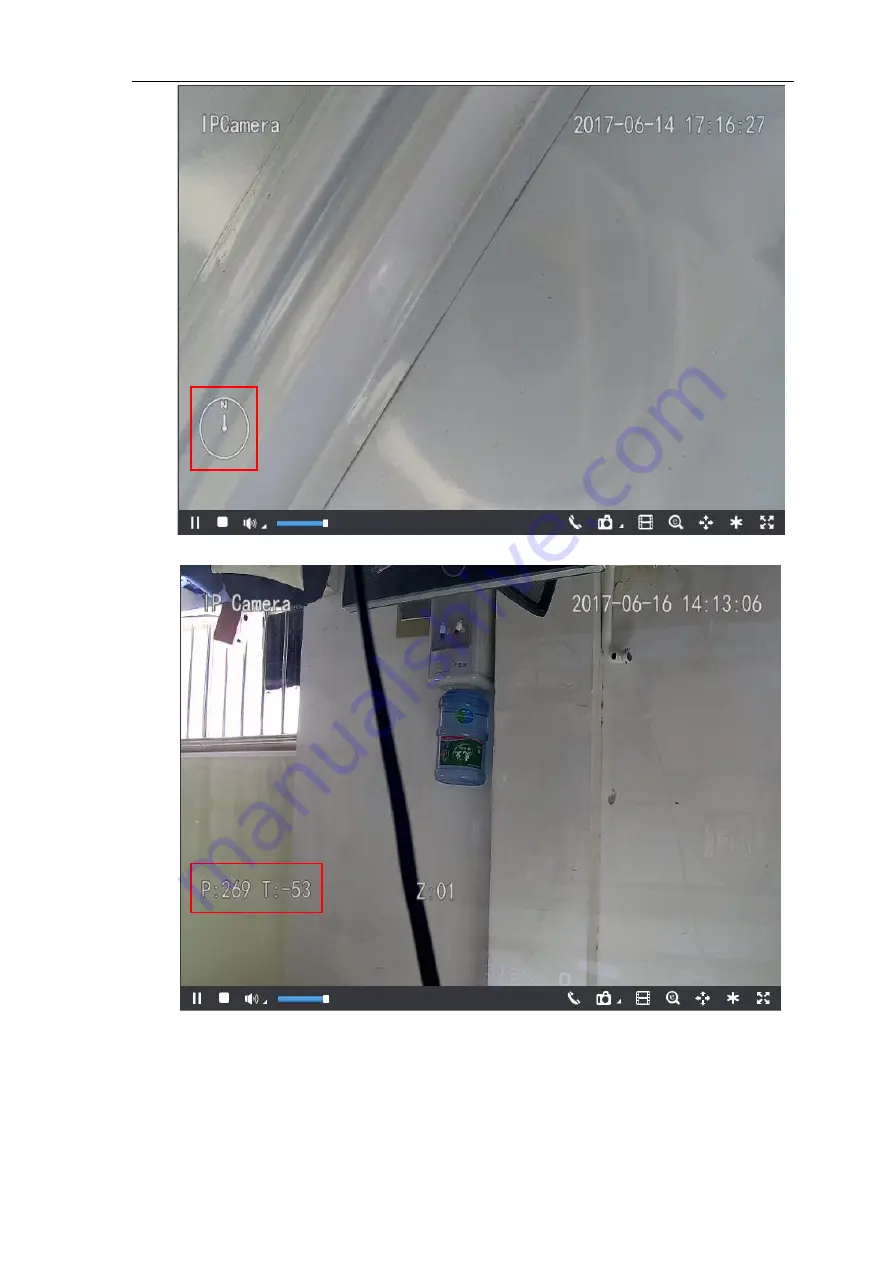
Picture 4-17 Azimuth Positioning- according to azimuth angle 


Picture 4-18 Azimuth Positioning- according to PT position 

4.3 Alarm Linkage 

Alarm  l

inkage is the system reaction after an alarm signal is received. It is to raise watch man’s attention to 

handle the event. 

Summary of Contents for IPC427-D120-N

Page 1: ...KEDACOM User Manual for HD IR Dome Camera Version 03 July 2017...

Page 2: ...eserved Without the prior written permission of Suzhou Keda Technology Co Ltd any reproduction translation or retransmission of all or any part of this document for any purpose in either electronic or...

Page 3: ...safety voltage range 2 If the product does not work properly please contact your dealer or the nearest service center Never attempt to disassemble or repair the product yourself in any way 3 Do not dr...

Page 4: ...to reduce damage efficiently such as thunder 1 The distance between the signal 2 wire and the high tension apparatus or high voltage cable should be at least 50m 3 Try to route cables along the eave w...

Page 5: ...2 3 Preset Position 18 4 2 4 Restricted Patrol 19 4 2 5 Path Mode 20 4 2 6 Mixed Mode 20 4 2 7 Scheduled Task 21 4 2 8 Positioning 22 4 3 Alarm Linkage 24 4 3 1 Motion Detection 25 4 3 2 Tampering 27...

Page 6: ...Settings 43 5 1 Network Access 43 5 1 1 Ethernet 43 5 1 2 PPPoE 43 5 2 Register to VMS 44 5 3 User Security 45 5 3 1 User Management 45 5 3 2 IP Filter 46 5 3 3 Security Service 46 5 4 Text Overlay 46...

Page 7: ...on Support WDR image setting 3D noise reduction motion detection image flip privacy mask Multi stream to fit different network bandwidth Configurable OSD on video image PTZ Built in high speed PTZ abl...

Page 8: ...HD IR Dome Camera User Manual 4 2 Product Appearance Picture 2 1 IR Dome Camera...

Page 9: ...l will take IE7 0 as an example 3 2 Initial Configuration 3 2 1 Modify Parameter 1 Get IPCSearch from the attached CD Picture 3 1 IPCSearch Notice Camera name is subject to the search result 2 Run IPC...

Page 10: ...ctivating the device Picture 3 3 Modify Parameter 5 Click OK and in the popup window click OK Wait for rebooting Picture 3 4 Reboot device 3 2 2 Login Web Client 1 After modification the device will r...

Page 11: ...environment suggest modifying the password monthly or weekly 3 Please keep your user name and password safe Picture 3 6 First login through web client 2 Input User Name and Password and click Login to...

Page 12: ...s the new password admin123 Click OK and the device will reboot 5 Re login to the web client by the new password To improve safety go to Settings System User Security User and modify password Refer to...

Page 13: ...HD IR Dome Camera User Manual 9 Picture 3 9 Web Client Interface...

Page 14: ...ar to adjust volume Click this button to disable voice and click again to enable voice Call Click this button to call camera and the volume slide bar appears Click again to stop calling Not all camera...

Page 15: ...k and drag toward lower right to draw an area The pixels of this area will be amplified and will cover the whole screen Left click and drag toward upper left to draw an area then the image will recove...

Page 16: ...Camera Image Exposure select DC IRIS Auto DC IRIS Manual for Aperture Mode and drag the slide bar of Aperture Sensitivity to adjust aperture Auto mode is suggested 4 1 2 3 Brightness The image will l...

Page 17: ...op down list of Dynamic Adjustment and drag the slide bar of Backlight Sensitivity When selecting Backlight Manual user can set or select Backlight Area in the live view image and the system will refe...

Page 18: ...enable 2D 3D Noise Reduction and drag the slide bar to adjust 2D 3D Noise Reduction level When selecting Disable this function will be disabled 4 1 2 7 Defog This function is suitable for outdoor fog...

Page 19: ...le wiper and click again to disable it The wiper will stop automatically after 10 brushes Click to enable it again if necessary 4 2 PTZ Control The camera is equipped with digital PTZ which is suitabl...

Page 20: ...perture and the image becomes bright Click on to narrow aperture and the image becomes dark Click on to adjust aperture automatically Auxiliary function buttons subject to actual models Click to enabl...

Page 21: ...is powered off it stays at a position for a certain period of time and this position is remembered by the system When the camera is powered again it can restore to the position before powering off If...

Page 22: ...Waiting Time is 1 minute by default configurable Panoramic Mode Camera patrols panoramically from 15 to 90 in tilt direction and from 0 to 360 in pan direction The Waiting Time is 1 minute by default...

Page 23: ...te to remove the preset ID 5 In the preset part of the Live View interface user can also select a preset ID to load set or clear Picture 4 8 Preset Position 4 2 4 Restricted Patrol Restricted Patrol i...

Page 24: ...y between the left and right restrictions only 4 2 5 Path Mode Path Mode means the camera patrols around all the valid preset patrol spots on a path After enabling this function click any PTZ control...

Page 25: ...Scheduled Task Check Enable 2 Input Task Recovery Time 5 720s Take 5s as example If user performs other PTZ operations during the task camera will recover the scheduled task in 5 seconds 3 Set schedu...

Page 26: ...and tilt directions Click Pan Tilt Zero Correction to perform Clicking the reset icon not only the pan and tilt directions will return to mechanical zero position but the digital movement of the camer...

Page 27: ...sic Config to select PTZ position display format display according to azimuth angle or PT position Picture 4 16 PTZ position display format 2 Rotate the PTZ camera to a specific position and click Azi...

Page 28: ...imuth Positioning according to azimuth angle Picture 4 18 Azimuth Positioning according to PT position 4 3 Alarm Linkage Alarm linkage is the system reaction after an alarm signal is received It is to...

Page 29: ...an alarm is triggered display alarm text on the screen Snapshot when an alarm is triggered capture the image automatically Need to install a storage card Alarm Output it means linking to an alarm outp...

Page 30: ...columns and 12 lines of small squares Click a square drag toward lower right and click Stop Then the area is the detected area and it turns purple red A camera can support max 4 motion detection areas...

Page 31: ...in Picture 4 14 Click Delete in Picture 4 18 or to cancel scheduled task Click to cancel all the scheduled tasks in one week Picture 4 21 Edit duration 5 Check Linkage Type It is the alarm output met...

Page 32: ...4 22 Tampering 4 3 3 Guard Line Enable this function in the interface to detect specific area at real time Once any object enters the guard line an alarm will be triggered Go to Settings Event Intell...

Page 33: ...r Manual 29 Picture 4 23 Guard Line Setting steps 1 Check Enable 2 If the intelligent function has linked to a preset it displays Already Set behind Enable Presets On this interface user can edit or d...

Page 34: ...guard area an alarm will be triggered Go to Settings Event Intelligent Function Enter Guard Area and configure Setting steps 1 Check Enable 2 If the intelligent function has linked to a preset it dis...

Page 35: ...uard Area Enable this function in the interface to detect specific area at real time Once any moving object leaves the area an alarm will be triggered Go to Settings Event Intelligent Function Exit Gu...

Page 36: ...o adjust the detection sensitivity to voice mutation The higher the Voice Intensity Threshold is the more sensitive it is to Voice Mutation 3 Duration user can set multiple durations and set different...

Page 37: ...nkage Abnormality linkage means the linkage triggered when abnormality occurs Abnormality type includes Disk Full Disk Error and Internet Disconnected Setting steps 1 Go to Settings Event Abnormality...

Page 38: ...same video source is encoded into different streams of videos with different resolutions User can select proper resolution to view or record according to the network bandwidth Go to Settings Camera V...

Page 39: ...The image is divided into 16 columns and 12 rows of small squares The max supported number of Privacy Mask area is 4 Setting steps for privacy mask areas 1 Go to Settings Camera Video Privacy Mask and...

Page 40: ...played Click Save Picture 4 30 Video info overlay 4 5 Snapshot Click Snapshot on the menu bar to enter snapshot management interface User can view or download snapshots in SD card An SD card must be i...

Page 41: ...clipping and video download as shown in Picture 4 2 Go to Settings Storage Storage Management to configure Disk Full Strategy Select the disk No and click Formatting to empty disk storage Picture 4 3...

Page 42: ...rface please confirm if an SD card has been rightly installed and then restart the web client 4 6 4 Download Enter video playback interface and download make sure an SD card has been rightly inserted...

Page 43: ...om SD card Clipping save path can be configured in Settings Local Setting Local Setting as shown in Picture 4 2 When the video is being played back click to start clipping and the button changes into...

Page 44: ...client the system will prompt to download the plug in Please refer to the Web Client Upgrade for details Method 2 1 Run IPCSearch and select the device from the list 2 Click Batch Processing Upgrade t...

Page 45: ...d operations on the web client please refer to the Help document 4 7 3 Restoration Go to Settings System System Maintenance and in the configuration management part there are options of Partial Restor...

Page 46: ...HD IR Dome Camera User Manual 42 Picture 4 37 Restoration...

Page 47: ...a access to network Camera accepts multiple methods via Ethernet and PPPoE to access to network The following will introduce how to configure camera network parameters through the web client 5 1 1 Eth...

Page 48: ...ect Model and fill in camera IP Keep other parameters as default and click OK Picture 5 3 VSIP Add front end device 2 Go to camera web client Settings Network Access Protocol VSIP as shown in the pict...

Page 49: ...Select user type from the dropdown list of User Type and assign operation authority to newly added user from the Authorization List Click Confirm Picture 5 6 Add user Notice 1 To ensure the safety of...

Page 50: ...ssword for the configured times the user IP will be locked up for a certain period of time during which the user cannot log in Picture 5 7 Security service 5 4 Text Overlay Display preset text on the...

Page 51: ...ad to load Default Font or other fonts Then edit content and position according to the above steps 4 Edit positions drag the items in the window with mouse to change their positions 5 Edit OSD texts f...

Page 52: ...IR Dome Camera User Manual 48 7 Click Save to save OSD setting The OSD will display in the set format If user selects Magnification the text will show in the magnified times Picture 5 10 Magnificatio...

Page 53: ...UXGA Resolution of 1600 1200 pixels 4 3 CIF Resolution of 352 288 pixels QCIF Resolution of 176 144 pixels HD High definition NAT Network Address Translation DHCP Dynamic Host Configuration Protocol...

Reviews: