background image

14 

KEBBY INDUSTRIES

CAP REMOVAL SETUP AND OPERATION

NOTE:    Cap will be destroyed during removal procedure. In order to use your new 

Kebby Power Crimp correctly for cap removal, use the following steps:

STEP 1:   Set the air pressure to zero psi. Turn the regulator adjustment knob (Figure 1-5) 

counter clockwise to decrease the air pressure to zero psi.


NOTE:    The knob is a push to lock, pull to unlock knob. If the knob will 

not turn, it may be in the locked position. To unlock the knob, 

pull up on the knob and push down on the knob to lock.

STEP 2:   Insert appropriate Power Head (sold separately) for de-capping into the Power 

Crimp assembly.


NOTE:    Caps with plastic tops cannot be de-capped with plastic in 

place. It must be removed before de-capping can take place.

STEP 3:   Insert the bottle and cap assembly into the 

Kebby Power Head De-capper with the pressure 
set to 30 psi and actuate the Power Crimp. Wait 
approximately 1 to 2 seconds before releasing 
the Power Crimp.


 If the cap did not come off, increase Crimp 
pressure 3 to 5 psi and repeat this step until the 
bottle is de-capped. Do not use more Crimp 
pressure than necessary.


 NOTE:    START CRIMP PRESSURE AT 30 PSI. 

INCREASE THE CRIMP PRESSURE 

IN SMALL INCREMENTS UNTIL THE 

CAP IS FULLY REMOVED.

 SETUP AND OPERATION

KEEP HANDS 

CLEAR OF MOVING 

PARTS.

WARNING

Summary of Contents for A10001

Page 1: ...DUSTRIES PowerCrimper Accessories Setup and Operation Manual KEBBY INDUSTRIES 4075 Kilburn Ave Rockford IL 61101 U S A Phone 815 963 1466 Fax 815 962 3490 Email sales kebbyindustries com www kebbyindustries com ...

Page 2: ......

Page 3: ...CCESSORIES 7 ASSEMBLY INSTRUCTIONS 8 ASSEMBLE POWER CRIMP TO CRIMP STAND 10 POWER CRIMP HEAD INSTALLATION 12 SETUP AND OPERATING CRIMP SET UP AND OPERATING INSTRUCTIONS 13 CAP REMOVAL SET UP AND OPERATING INSTRUCTIONS 14 MAINTENANCE PREVENTIVE MAINTENANCE 15 STANDARD MAINTENANCE CHARTS 15 MACHINE CLEANING 16 PNEUMATIC SYSTEM 16 PNEUMATIC SYSTEM PREVENTIVE MAINTENANCE 17 EFFECTS OF CONTAMINATES ON ...

Page 4: ... quality of the crimp makes the Power Crimp very cost effective Kebby Industries feels that once you have used the Kebby Power Crimp and accessories you will not want to go back to hand crimping PROPRIETARY AGREEMENT This manual discloses information in which Kebby Industries has proprietary rights Neither receipt nor possession of this manual confers or transfers any right to the client and by it...

Page 5: ...otentially hazardous if safety precautions are not followed Throughout this manual you will be reminded of safety factors CAUTION STORED ENERGY THIS WARNING SIGN IS A REMINDER THAT THERE IS DANGER TO PERSONNEL BE VERY CAREFUL THIS CAUTION SIGN DENOTES CARE MUST BE TAKEN OR EQUIPMENT MAY BE DAMAGED THIS SIGN IS USED WHEN DANGEROUS STORED ENERGY MAY BE PRESENT THIS WILL REQUIRE ADDED CAUTION AND A W...

Page 6: ...nted and locked and the workpiece is securely positioned before starting the unit 7 Never operate any unit beyond its rated speed or capacity 8 Never reach across or under any moving machine part 9 Do not wear loose clothing or jewelry that could become entangled in the moving parts of the unit 10 Never lay tools or tooling on the unit where it might interfere with the operation of the unit 11 Alw...

Page 7: ...nit complies with the Occupational Safety and Health Act of 1970 standards where the requirements are specific The balance of the standards are complied with as interpreted by Kebby Industries Since these standards are continually evolving and since they are subject to considerable interpretation by a third party Kebby Industries cannot guarantee or warrant compliance with the provisions or standa...

Page 8: ...P N A10007 Air Supply Hose P N A10008 Air Supply Hose SS Braided P N A10009 Power Crimper Stand P N A10010 Stainless Steel Base Model P N A10010 1 Foot Pedal Assembly w hose P N A10011 Hanger Assembly P N A10012 Verification Gauge Assembly P N A10013 Lubricating Grease P N A10024 Inter Changeable Crimping and Decapping Heads available for a wide variety of cap sizes and styles from 7 5mm to 32mm A...

Page 9: ... POLYURETHANE SELF STORING HOSE ASSEMBLY 1 A10008 POLYURETHANE STRAIGHT HOSE ASSEMBLY 1 A10009 BRAIDED STAINLESS STEEL HOSE ASSEMBLY 3 1 A10011 FOOT PEDAL ASSEMBLY 4 1 A10005 SUPPLY AIR HOSE ASSEMBLY 5 1 A10002 GAUGE REGULATOR ASSEMBLY 6 1 A10010 POWER CRIMP STAND ASSEMBLY 7 1 A10013 AIR PRESSURE VERIFICATION ASSEMBLY KEBBY POWER CRIMP AND ACCESSORIES ASSEMBLY ...

Page 10: ...nect the Power Crimp Hose Assembly to the Power Crimp as follows Step 1 Install the hose fitting onto the Power Crimp adapter Step 2 Place a 1 2 open end wrench on the adapter of the Kebby Power Crimp Hold the 1 2 wrench stationary and tighten the hose fitting NOTE Do not over tighten the fitting Minimum pressure is needed to secure the fitting FIGURE 1 2 8 KEBBY INDUSTRIES ASSEMBLY ...

Page 11: ...9 STEP 3 Attach main supply air less than 36 relative humidity 60 degrees F to the Gauge Regulator STEP 2 Connect the Power Crimp Hose Assembly to the Gauge I Regulator FIGURE 1 3 ASSEMBLY DO NOT EXCEED 250 PSI WARNING ...

Page 12: ...ssembly STEP 4 Align the Power Crimp with the Crimp Stand and slide the Power Crimp down and into the Crimp Stand Assembly STEP 5 Hold the Power Crimp in place and swing the hinged cover closed Finger tighten clamp thumb screw STEP 6 Install the verification nut onto the Kebby Power Crimp adapter Hold the 1 2 wrench stationary and tighten the nut using a 9 16 open end wrench ASSEMBLE POWER CRIMP T...

Page 13: ...ing Minimum pressure is needed to secure the fitting STEP 8 Connect the Power Crimp Hose fitting to the quick disconnect of the Foot Pedal Assembly STEP 9 Connect the Supply Hose to the quick disconnect fitting on the Foot Pedal Assembly STEP 10 Connect the Supply Hose Assembly to the Gauge Regulator Assembly STEP 11 Attach main air supply less than 36 relative humidity 60 degrees F to the Gauge R...

Page 14: ...t appropriate Power Head sold separately by turning to the right to tighten left to loosen NOTE Do not over tighten the Power Head Minimum pressure is needed to secure the Power Head FIGURE 1 7 WHEN INSTALLING OR REMOVING POWER CRIMP HEAD SET AIR PRESSURE TO 0 PSI WARNING ...

Page 15: ...ssure set to 15 psi and actuate the Crimp Wait approximately 1 to 2 seconds before releasing the Crimp Inspect cap for proper seal If seal is not crimped to meet your requirements increase the air pressure by turning the knob clockwise at approximately 2 to 3 psi increments until seal meets your requirements Remove crimped seal or partially crimped seal replace with new seal and stopper if necessa...

Page 16: ...propriate Power Head sold separately for de capping into the Power Crimp assembly NOTE Caps with plastic tops cannot be de capped with plastic in place It must be removed before de capping can take place STEP 3 Insert the bottle and cap assembly into the Kebby Power Head De capper with the pressure set to 30 psi and actuate the Power Crimp Wait approximately 1 to 2 seconds before releasing the Pow...

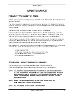
Page 17: ...ed by Kebby Industries will simplify the care and handling of the machine and help you obtain maximum benefits from your new machine Any questions or comments regarding the operation or maintenance of your machine are welcome and will be handled promptly by our service department at any time KEBBY INDUSTRIES 4075 Kilburn Avenue Rockford Illinois 61101 USA Phone 815 963 1466 Fax 815 962 3490 Sales ...

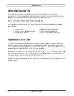
Page 18: ...bly Power Crimp Stand Assembly MAINTENANCE PNEUMATIC SYSTEM Preventive maintenance of the pneumatic system requires a clean dry less than 36 relative humidity 60 degrees F shop compressed air supply Experience has shown that foreign material lodging in the air supply valves is a major cause of breakdowns This contamination of the system will occur from two sources The first occurs naturally inside...

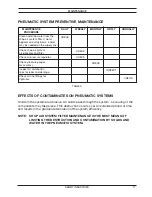
Page 19: ...YSTEM FILTER MAINTENANCE IS THE BEST MEANS OF LIMITING THE DESTRUCTION AND CONTAMINATION BY SOLIDS AND WATER IN THE PNEUMATIC SYSTEM MAINTENANCE DAILY WEEKLY MONTHLY QRTLY ANNUALLY PROCEDURE Clean and drain water from the CHECK shop air system filter If water appears on a daily basis a dryer may be needed on the supply line Check shop air system CHECK air lubricator and filter Check air pressure r...

Page 20: ...KEBBY INDUSTRIES 4075 Kilburn Ave Rockford IL 61101 U S A Phone 815 963 1466 Fax 815 962 3490 Email sales kebbyindustries com www kebbyindustries com ...

Reviews: