16
CP-Parameter for open-loop operation
CP18 Switching frequency
Co-domain
Setting Description
2 / 4 / 8 / 12 /
16 kHz
LTK
The switching frequency with which the power modules are
clocked can be changed depending on the application. The
max.possible switching frequency as well as the factory setting
are specified by the power circuit. The values must be con
-
firmed with „ENTER“.
Refer to following list to
learn about influences and
effects of the switching fre-
quency.
low switching frequency
high switching frequency
less inverter heating
less noise development
less discharge current
improved sine-wave simula-
tion
less switching losses
less motor losses
less radio interferences
improved controller charac-
teristics
improved concentricity with low
speed (only open loop!)
Attention
At switching frequencies above 4 kHz pay absolute attention to the
max. motor line length in the technical data of the power circuit manual.
CP19 Step value 1
CP20 Step value 2
CP21 Step value 3
Co-domain
Setting Description
CP19
0…±400 Hz
5 Hz
Three fixed frequencies can be adjusted. The selection
is made by the inputs I1 and I2. If adjustments are made
that are outside the fixed limits of CP10 and CP11, then
the frequency is internally limited. The negative values
are released in application mode.
CP20
50 Hz
CP21
70 Hz
Info
Input I1
→
step value 1
Input I2
→
step value 2
Input I1 and I2
→
step value 3
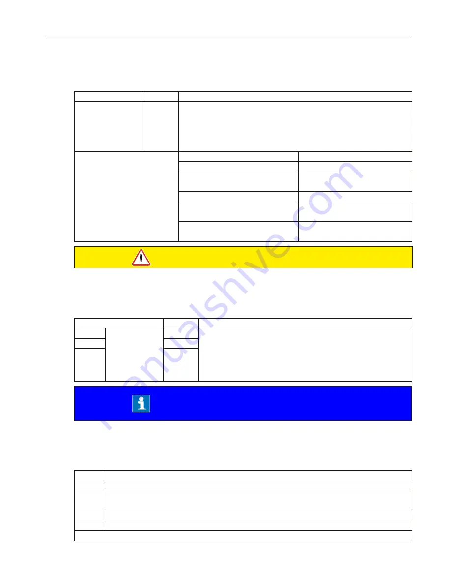
CP22 DC braking mode
With DC-braking the motor is not decelerated by the ramp. Quick braking is caused by D.C.
voltage, which is applied onto the motor winding. This parameter determines how the DC
braking is triggered.
Value Activation
0
DC-braking deactivated
1
DC-braking at switch off of the direction of rotation and upon reaching 0 Hz. The
braking time corresponds to CP23 or up to the next rotation setting.
2*
DC-braking as soon as setting for the direction of rotation is absent.
3*
DC-braking as soon as the direction of rotation changes or is absent.
further on next side
Summary of Contents for COMBIVERT G6
Page 2: ......


