
8
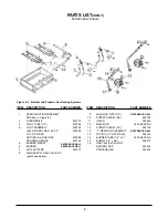
ITEM
DESCRIPTION
P/N
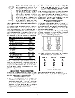
1
CONTROL PANEL FRAME 1-800-KEATING
2
GREASE DRAWER
30" & 36" Deep
052505
3
SWITCH, ROCKER
035030
4
SPARK IGNITER WITH ELECTRODE
(NO BRACKET)
008327
5
CONTROL PANEL INSERT
1-800-KEATING
6
THERMOSTAT 400°F
017370
THERMOSTAT 550°F
023897
THERMOSTAT
REPLACEMENT KIT 400°F
037088
7
THERMOSTAT KNOB 400°F, Black
060612
THERMOSTAT KNOB 550°F, Black
038368
8
DIAL PLATE 400°F
034870
DIAL PLATE 200°- 500°F
060105
9
GAS VALVE MILLIVOLT
NAT.
023625
L.P.
023624
10
TAN KNOB ON GAS VALVE
004803
11
SCREW FOR TAN KNOB
004805
(NOT SHOWN)
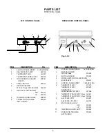
ITEM
DESCRIPTION
P/N
1
CONTROL PANEL INSERT
1-800-KEATING
2
DIAL PLATE 200°- 500°F
060105
3
THERMOSTAT 550°F 023897
THERMOSTAT KNOB, BLACK
038368
4
TOGGLE SWITCH SEALED
059141
ON/OFF
5
SPARK IGNITOR
008327
6
GREASE DRAWER
30" & 36" Deep (NOT SHOWN)
052505
7
GAS VALVE (NOT SHOWN)
NAT.
023625
L.P.
023624
8
TAN KNOB ON GAS VALVE
004803
9
SCREW FOR TAN KNOB
004805
(NOT SHOWN)
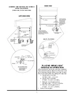
PARTS LIST
MIRACLEAN
®
Griddle
1
2
3
4
5
5
6, 7, 8
9
10
ON
OFF
ON
OFF
C
OT
F
A
T
B
IL R A
I
E S H
T
250
200
450
350
300
400
500
C
OT
F
A
T
B
IL R A
I
E S H
T
250
200
450
350
300
400
500
1
2
3
4
4
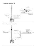
Figure 6-2
2011 CONTROL PANEL
SERIES 2000 CONTROL PANEL
Summary of Contents for SERIES 2000
Page 17: ......