24
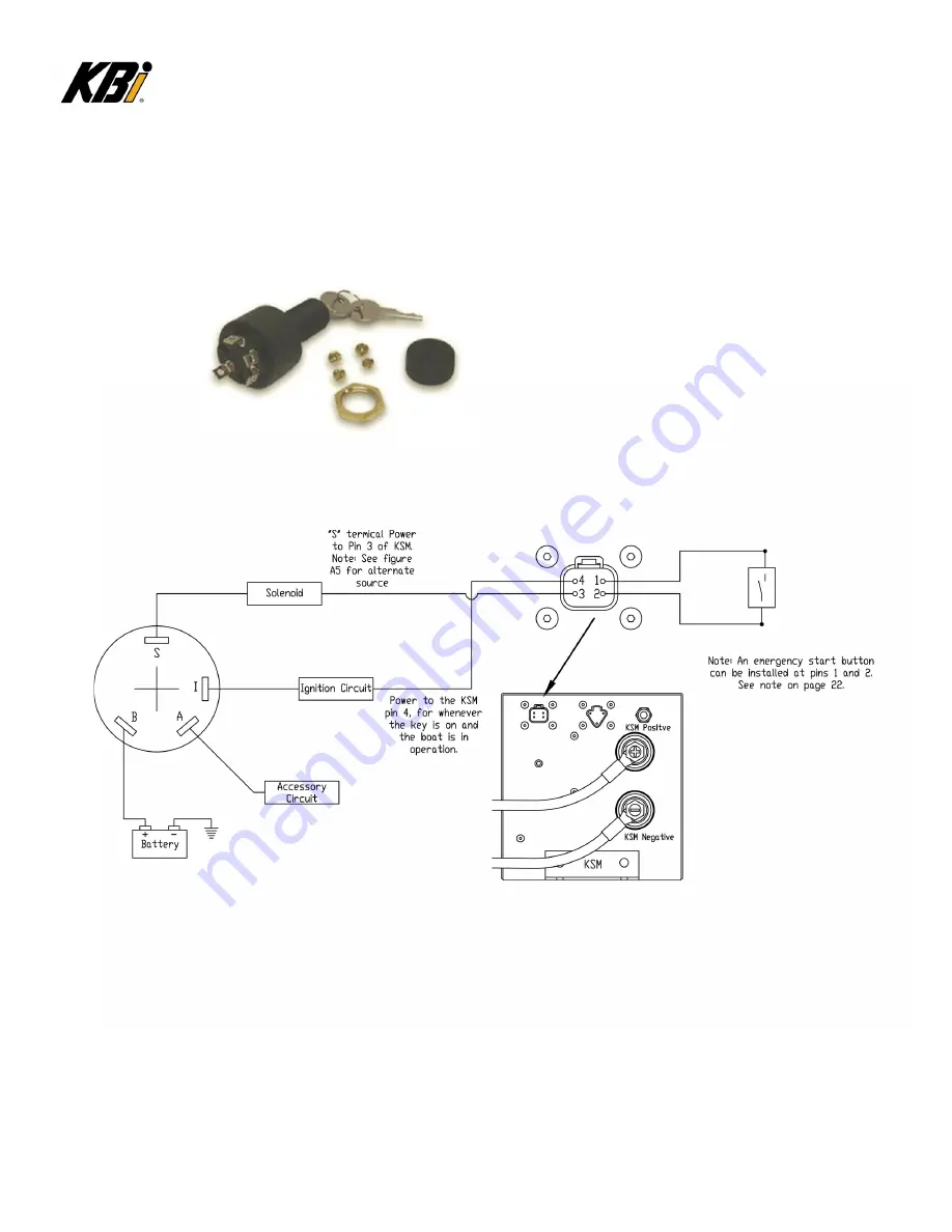
The PLC inside the KSM needs power at pin four from a source, such as the key-switch, that
provides power only when the boat is in operation. See Figure A2.
Example of existing key-switch.
Figure A2: Typical Boat Key-Switch Schematic
NOTE:
“S” terminal receives power when the key-switch initiates an engine starting event.
The power is also supplied to Pin 3 of the KSM, bringing the KSM online to supply
engine starting power.
Summary of Contents for KSM
Page 10: ...10 Figure 2 Typical Cable Installations ...
Page 11: ...11 Figure 3 Six 6 Cell KSM ...
Page 12: ...12 Figure 4 Ten 10 and Twelve 12 Cell KSM ...
Page 17: ...17 Figure 7 Standard MKSM Schematic ...
Page 23: ...23 Figure A1 Typical Cable Installations ...
Page 25: ...25 Figure A3 Schematic Alternate Source for Start Signal ...
Page 27: ...27 Figure B1 Typical Cable Installations ...
Page 29: ...29 Figure B3 Simplified Installation Diagram ...
Page 30: ...30 Figure B4 Standard DPST Install ...
Page 32: ...32 Figure C1 Typical Cable Installation ...
Page 33: ...33 Figure C2 Alternate Method ...


