KBC WAP Operation Manual Download Page 9


Wireless Ethernet PtP & MP System Operations Manual 


WEM INSTALLATION & OPERATION (CONTINUED) 


C.


CONFIGURE CABLE 
Determine the length of Cat5 cable that will be needed and where the PIM will 
be located. The total length of cable from the WEM to the Ethernet device 
cannot exceed 100 meters (325 feet), however, the PIM can be located 
anywhere along the overall 100m of cable. 
 
Slide the weatherproof connector over the cable jacket before crimping the 
connector. See below for color-code standards to configure the correct type of 
Ethernet cable.  
 
Ethernet standard straight-through cable configurations used must be 
configured to one of the Ethernet standards (568-A or 568-B) in order for the 
WES system to operate efficiently. Any deviation from one of the two standard 
configurations can lead to undesired activity. 
 
Pin out for color codes 568-A and 568-B: 

568-A  


568-B 

1- Green/White 


1- Orange/White 

2- Solid Green 


2- Solid Orange 

3- Orange/White 


3- Green/White 

4- Solid Blue  


4- Solid Blue 

5- Blue/White 


5- Blue/White 

6- Solid Orange 


6- Solid Green 

7- Brown/White 


7- Brown/White 

8- Solid Brown 


8- Solid Brown 


A cable configured with the 568-A color code on one end and the 568-B color 
code on the other end is an Ethernet standard crossover cable. 
 
Connect the RJ-45 connector into the WEM’s LAN port. Slide the strain relief 
back up the cable to the threaded port in the case and screw it into the 
Host/Client and tighten.  Tighten the clamping nut until the CAT5 cable is 
sealed in the connector.  The weatherproof strain relief should be tight to the 
case but the opening should remain loose enough to enable condensation 
release. 
 

D.


CONNECT HOST AND CLIENT(s) 
Verify antenna alignment and LED status. See page 5 for applicable LED 
activity. Ensure the green power LED on the PIM is illuminated. The WEM red 
power LED should be on provided the cable into the LAN port is seated in 
properly. If multiple Clients connect to one multipoint Host, verify all Clients 
are on the same frequency as the MP Host and pointed in its direction. 
 

E.


ESTABLISH LINK 
Follow above steps, A through D, for all WEMs of the system to be established.  


NOTE:    In  some  cases,  depending  on  the  physical  and  RF  environment,  a 
useable  throughput  rate  may  not  be  possible.    Contact  KBC  for  more 
information – 888-366-4276 or [email protected].      


Wireless Ethernet PtP & MP System Operations Manual 


ADVANCED OPERATION 

 
WEB BROWSER INTERFACE 

Each  Host  and  Client  has  a  web  browser  interface  to  access  the  advanced  setup 
functions.    If  changing  advanced  settings,  be  sure  to  connect  and  power  the  radios 
individually.    To  access  this  interface,  connect  the  WES  to  the  Ethernet  port  on  a 
computer,  launch  the  web  browser  and  type  in  the  default  IP  address  at 

http://192.168.1.200

  for  the  Host  and 

http://192.168.1.201

  for  the  Client.  The 

configuration  of  the  computer  used  to  access  the  WEM  may  need  to  be  changed 
depending  on  its  IP  settings.    The  IP  address  of  the  computer  should  be  set  to 
192.168.1.xxx.    The  xxx  setting  can  be  any  address  2  –  254  excluding  200/201  or 
any  other  IP  address(s)  you  wish  to  use  for  a  WEM  on  that  subnet  (or 
Encoder/Decoder/WES  Mesh/ThruLink  product  if  applicable).    The  Subnet  mask 
should  be  255.255.255.0.    If  you  have  any  questions  or  concerns  about  changing 
these settings, please contact your network administrator.   
 
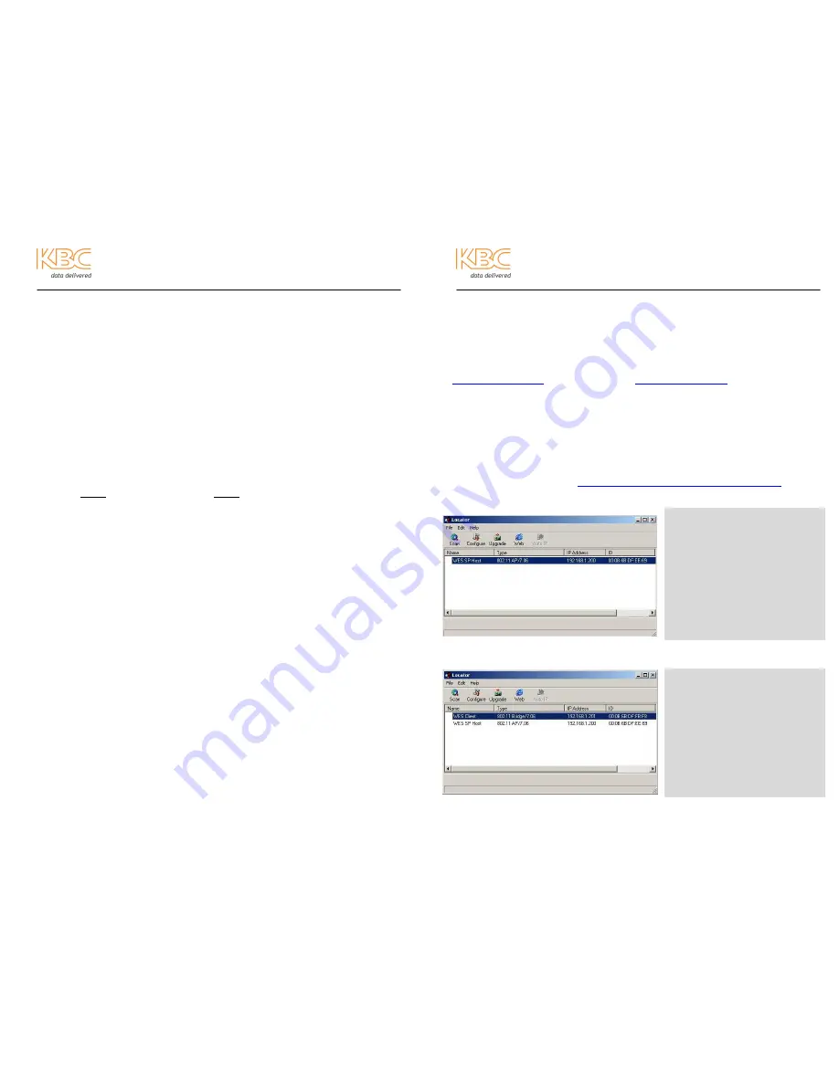
LOCATOR SOFTWARE TOOL – AVAILABLE FOR DOWNLOAD ONLINE 
Available on our web site at 

www.kbcnetworks.com/softwaredownloads.htm

 is a tool 

that can search for the WES unit IP address. The tool can locate the WEM regardless 
of the subnet setting of the computer on which it is running.  


Connect  to  the  Host  and  click  “Scan”.  Upon  wireless  connection  to  the  Client,  the 
remote unit will appear after the clicking “Scan” again. 


Click  “Web”  or  double-click  any  of  the  WES  devices  to  access  the  internal  GUI 
interface. 


FAQ:  What  does  the  yellow 
icon  next  to  the  “WES  Client” 
or  “WES  SP/MPHost”  device 
indication mean? 

An 

<

<

!

!

>

>

  icon  next  to  the  device 

indicates  an  Ethernet  issue.  If 
your computer’s static IP address 
is  set  to  a  different  subnet  than 
the  WEM,  the  icon  will  appear. 
Duplicate  IPs, network loops, low 
signal  strength  and  several  other 
reasons are other possibilities. 

FAQ: What is the “AutoIP”? 

If  the  yellow 

<

<

!

!

>

>

  icon  appears, 

the  “AutoIP”  button  will  be 
available.  Click  the  icon  to  hi-
light in blue. Then click “AutoIP”. 
This function will change the IP of 
the  WEM  to  match  the  subnet  of 
the  connected  computer.  After 
approximately  10  seconds,  click 
“Scan”  and  the  new  IP  address 
should appear without the icon. 

Summary of Contents for WAP

Page 1: ...297 4930 Fax 1 949 297 4933 KBC Networks Ltd EMEA Carlton Suite Barham Court Teston Maidstone Kent ME18 5BZ United Kingdom Office 44 0 1622 418782 Fax 44 0 20 7100 8147 Email info kbcnetworks com Web www kbcnetworks com Wireless Ethernet Point to Point Multipoint Systems Operations Manual Version 20111027 ...

Page 2: ...odule WAP WAPOM or subscriber unit WSU WSUP WSUDI WSUOM Qty 1 PIM Qty 1 PS 500 A Qty 1 LNBMB excluded in WAPOM or WSUOM Qty 1 Strain Relief for Ethernet cable connection at RJ 45 LAN port of WES module Qty 1 Operations manual P 1 Wireless Ethernet PtP MP System Operations Manual PREFACE CONTINUED TECHNICAL SUPPORT AVAILABILITY This manual is comprehensive to the extent that it will answer many of ...

Page 3: ...ANT SAFETY INSTRUCTION For your protection please read and observe all safety instructions before operating this system and keep this sheet and any additional instructions for future reference INSTALLATION USE OBSERVE WARNINGS All warnings in the operating instructions should be carefully followed Do not make any modifications to the Wireless Ethernet Module WEM Power Injection Module PIM or any o...

Page 4: ...it not expressly approved by the party responsible for compliance could void the users authority to operate the equipment Changes or modifications not expressly approved by KBC could void the users authority to operate the equipment iii Wireless Ethernet PtP MP System Operations Manual FCC POWER OUTPUT RESTRICTIONS The FCC does not require licensing to implement this device License free operation ...

Page 5: ...otherwise noted The channels of each set of Host Clients must be matched for the radios to communicate with each other For multi connect devices each Client must be set to the same channel as the Host that it will be connected to If connecting more than one Client to a single Host please see the advanced operation section of this manual for multipoint setup 2 Mount the Client at the remote locatio...

Page 6: ...y of IP cameras DVR NVRs managed non managed switches encoders decoders and web servers to be used across long range wireless line of sight links A FRONT VIEW 1 Module case 2 Antenna cover B REAR VIEW 1 Serial Number 2 List of Available Frequencies 3 Channel Selector on side of WEM Factory set to channel 0 unless otherwise noted 4 Status LEDs Amber Link Activity Red Power Green Signal Level 5 LAN ...

Page 7: ...LED responses determined by the type of product in use POINT TO POINT HOST LED ACTIVITY WES 2500 WES 2 4 Hosts If the green LED flashes at any rate it is indicating a less than max signal connection MULTIPOINT HOST LED ACTIVITY WAP WAPOM CLIENT LED ACTIVITY All Clients from all part numbers excluding WAP WAPOM The Client LED status will remain the same regardless of the type of host to which it is...

Page 8: ...diagram to the left 3 Power cycle device to implement channel change 4 Reseal port by replacing weatherproof plug B MOUNT DIRECTIONAL HOST CLIENT Mount the Host Client using the included wall pole mount bracket and hardware Connect the black mounting assembly with adjustment swivel to mounting L shaped bracket with the 20 button head screw Connect the unit to the mounting assembly using the mounti...

Page 9: ...ending on the physical and RF environment a useable throughput rate may not be possible Contact KBC for more information 888 366 4276 or info kbcnetworks com 8 Wireless Ethernet PtP MP System Operations Manual ADVANCED OPERATION WEB BROWSER INTERFACE Each Host and Client has a web browser interface to access the advanced setup functions If changing advanced settings be sure to connect and power th...

Page 10: ..._____ Subnet Mask The filter used for association of Ethernet devices _________ WIRELESS MAC Address The MAC address of the radio Record this information for tracking purpose __________________________________ Current Trans Rate The Client will display its signal rate to the Host Max is 54 _ Current Frequency Client Current frequency scanned for AP________________ Turbo Mode Available on 5765 5805...

Page 11: ...ped or collided packets As the system continues to run these numbers will accumulate until cleared to 0 Refresh to see updated statistics ETHERNET STATISTICS Packet information at the motherboard and cable level If packets are dropped or collided at the Ethernet level then there could be a problem with the cabling or other LAN related hardware WIRELESS STATISTICS Packet information across the wire...

Page 12: ...EL SWITCH OVERRIDE A drop down list of frequencies will appear Make sure that if changing frequencies using a connected wireless link the channel on the opposite end is configured first For units with the 25 5 dBi jumper ON selecting 5280 5300 or 5320 will default to 5745 as only 5745 5825 is available 2 Wireless Security Mode The WES can be configured to various forms of wireless encryption and c...

Page 13: ...vice name for the Host and or Client ADMIN PASSWORD To change the password type in the desired password change and confirm Record all password changes as there are no ways to reset to default later if the password is lost or forgotten ADMINISTRATION The device name can be changed here Each unit does not have to have a matching device name in order to associate This name will appear on the status i...

Page 14: ...itch Super Mode Disabled Encryption Cipher WPA 2 AES Device Name WES SP Host WES MP Host WES Client depends on software type 18 Wireless Ethernet PtP MP System Operations Manual ADVANCED OPERATION CONTINUED H ADVANCED FIRMWARE This page is used to flash firmware updates when necessary FIRMWARE INFORMATION Current firmware is 7 06 for all units using channel selector switches that have 8 positions ...

Page 15: ...ni WAPOM WSUOM 2 5 dBi 5 8 GHz Small patch WES 2500 WAP WSU 7 8 dBi 5 8 GHz Large patch WES 2 4 WSUP 16 7 dBi 5 8 GHz Small patch in 18 inch parabolic dish 24 dBi 5 8 GHz Beam Width Omni 360 Small Patch 90 Large Patch 24 Dish 8 Data Throughput Rate Up to 20 Mbps Standard Mode Up to 50 Mbps Super Mode FCC ID JRRWES IC 4887A WES MANAGEMENT Interface 10 100 Base T half full duplex rate auto negotiate...

Page 16: ... WEMs are aimed properly You should have clear wide open line of sight between the WEM modules Try a different frequency and cycle power Verify sufficient voltage into each PIM If MP Host the green LED should flash see page 5 Problem Suggestion All three solid LEDs but no video Check video at the camera Check wiring into encoders or decoders Try a different frequency and cycle power Connect one WE...

Page 17: ...n implied warranty lasts so the above exclusions or limitations may not apply to you f If you do not wish to be bound by any of the provisions in this warranty please return the product s immediately 3 Contact your dealer regarding return authorizations for out of warranty repairs and any further product information 24 Wireless Ethernet PtP MP System Operations Manual APPENDIX The appendix section...

Page 18: ... Address Remote Location 2 Head End Location in Single Point to Point Application Device S N Host Client IP Address Radio MAC Address Remote Location 3 Device S N Host Client IP Address Radio MAC Address Remote Location 4 Device S N Host Client IP Address Radio MAC Address Head End Location Device S N Host Client IP Address Radio MAC Address A 2 ...

Reviews: