KB Electronics KBPC-240D Installation And Operation Manual Supplement Download Page 13

10

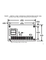
FIG. 8 – CONNECTION DIAGRAM

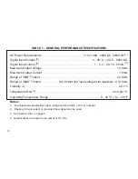
FIG. 7A – CAPTIVE SCREW

TIGHTENED IN CASE

FIG. 7B – CAPTIVE SCREW

ENGAGED IN FRONT COVER

IV. WIRING.


Warning!  Read Safety Warning before attempting to use this control.

Warning!  To avoid erratic operation do not bundle AC Line and motor wires with

potentiometer, voltage following, enable, inhibit or other signal wiring.  Use shielded

cables on all signal wiring over 12" (30 cm) – Do not ground shield.

Wire control in accordance with the National Electric Code requirements, and other codes that

apply.  Be sure to fuse each conductor which is not at ground potential.  

Do not


fuse neutral

or grounded conductors

.  Note:  See section V, Fusing, on page 13.  A separate AC line

switch, or contactor, must be wired as a disconnect switch, so that the contacts open each

ungrounded conductor.  An accessory ON/OFF AC Line Switch (KB P/N 9341) may be

installed in this control in lieu of, or in addition to, the Start/Stop Switch normally provided.

The switch can be wired for double pole or single pole operation.  (See fig. 8, for AC Line and

Armature connection.)

To maintain the watertight integrity of the control, be sure to use suitable watertight connectors

and wiring, which are appropriate for the application.  Two .875" (22.2 mm) knockout holes are

provided for a standard 1/2" knockout connector (not supplied) for wiring.  A watertight plug

is provided if only one knockout is required.

A. AC Line –

 Connect AC Line to terminals L1 and L2.  (Be sure jumpers J2A and J2B are

set to the correct position to match the AC line input voltage.  See table 8 on page 11.

TABLE 7 – TERMINAL BLOCK WIRING INFORMATION

Terminal Block

Designation

Connection

Designation

Supply Wire Gauge*

Maximum Tightening

Torque (lbs inch)

Minimum

Maximum

TB1

A1, A2, L1, L2

22

12

12

TB2

F1, F2

22

14

3.5

TB3

T+, T–

22

14

3.5

*Use Cu wire only (AWG)

B. Motor Armature – 

Connect motor armature

to terminals A1 (+) and A2 (–).  (Be sure

jumper J3 is set to closely match motor

voltage.  See table 8, p. 11.)  

WARNING!

  Do

not wire switches or relays in series with the

armature.  

Armature switching can cause

catastrophic failure of motor and/or

control.


Do not bundle AC and motor

wires with other wires (e.g.,

potentiometer, analog input, Forward-

Brake-Reverse, etc.).

CAPTVE SCREW

COVER

GASKET

CASE

CAPTVE SCREW

COVER

GASKET

CASE

Summary of Contents for KBPC-240D

Page 1: ...has been added which can be used to turn equipment on or off as a function of drive status Off Stop Run The General Performance Specifications Electrical Ratings Mechanical Specifications and Connecti...

Page 2: ...AND OPERATING INSTRUCTIONS MODEL KBPC 240D KB Part No 9338 Black Case Part No 9342 White Case NEMA 4X IP 65 SCR Speed and Torque Control Designed For DC Motors Rated 1 50 1 HP 90VDC 1 25 2 HP 180VDC...

Page 3: ...e Input and Motor Voltage with J2 and J3 Jumper Position 10 9 Field Connections Shunt Wound Motors Only 11 10 Armature Fuse Chart 13 11 Parts List 17 18 FIGURES 1 Control Layout 3 2 Mechanical Specifi...

Page 4: ...and F2 Connect half voltage field wires 90 volt motors with 50 volt fields and 180 volt motors with 100 volt fields to F1 and L1 See sec IV C on page 11 2 SPEED OR TORQUE MODE Jumper J1 is factory set...

Page 5: ...laration of Conformity Installation of a CE approved RFI filter KBRF 200A KB P N 9945A or equivalent is required Additional shielded motor cable and or AC line cables may be required along with a sign...

Page 6: ...3 FIG 1 CONTROL LAYOUT Illustrates Factory Setting of Jumpers and Approximate Trimpot Settings...

Page 7: ...4 INCHES mm FIG 2 MECHANICAL SPECIFICATIONS TM TM...

Page 8: ...Line VDC IR Comp Range at 230VAC Line VDC CL Range Range Setting Timed CL Range Sec Voltage Following Linearity Base Speed 115 or 230 50 60 1 0 90 0 180 0 90 100 50 200 100 1 50 1 015 75 1 25 2 03 1 5...

Page 9: ...motor load exceeds the torque setting the motor will stall the Overload LED will light and the drive will apply a constant preset torque based on the potentiometer setting The Overload LED will light...

Page 10: ...D TORQUE MODE B J2A J2B Input AC Line Voltage Select proper input line voltage 115VAC or 230VAC by placing both J2A and J2B in the correct corresponding positions 115V or 230V C J3 Armature Voltage Ou...

Page 11: ...ting Application Note Subfractional Horsepower Motors For subfractional motors with current ratings below 2 5 amps the KBPC can be modified as follows Note Before making this modification you must hav...

Page 12: ...Base speed of motor in RPM Note For tach generator feedback Jumper J3 must be in the T position G J7 Signal Input Voltage The output of this control is normally controlled with the main potentiometer...

Page 13: ...AC Line and Armature connection To maintain the watertight integrity of the control be sure to use suitable watertight connectors and wiring which are appropriate for the application Two 875 22 2 mm k...

Page 14: ...ains powered without motor rotating for an extended period of time TABLE 9 FIELD CONNECTIONS Shunt Wound Motors Only AC Line Voltage VAC Motor Voltage Field Voltage VDC Field Connection 115 90 100 F F...

Page 15: ...be installed Model KBSI 240D P N 9431 see figure 17 p 20 for signal isolator wiring diagrams Connect the isolated input voltage to terminal P2 and P1 See fig 12 Note Be sure jumper J7 corresponds to...

Page 16: ...ture fuse is not supplied and must be installed for control to operate VI OPERATION WARNING Read Safety Warning on page 2 before attempting to operate the control or severe injury or death can result...

Page 17: ...oximately seven 7 seconds and full rotation is approximately fifteen 15 seconds D Deceleration DECEL The DECEL trimpot sets the amount of time it takes the control to go from full speed to minimum spe...

Page 18: ...the AC line is connected to the control B Stop Indicator STOP This lamp will glow YELLOW when the control is placed in the STOP mode with the Start Stop Switch C Overload Indicator CL When the motor i...

Page 19: ...hased seperately E ON OFF AC Line Switch P N 9341 This option is desirable if a positive AC Line disconnect is required The switch can be installed in lieu of the Start Stop Switch which can be easily...

Page 20: ...20 FIG 17 CONNECTION DIAGRAMS FOR KBPC 240D WITH KBSI 240D SIGNAL ISOLATOR...

Page 21: ...21 APRM PC Electronic FWD BRK REV FIG 18 INTERNAL CONNECTION DIAGRAM FIG 19 CONNECTION DIAGRAMS FOR AVAILABLE OPTIONS...

Page 22: ...ee expressed or implied and we are not responsible for any expense including installation and removal inconvenience or consequential damage including injury to any person caused by items of our manufa...

Page 23: ...ety Warning on Page 1 The information contained in this manual is intended to be accurate However the Manufacturer retains the right to make changes in design which may not be included herein TM A COM...

Page 24: ...nection 5 2B 230V Connection 5 3 Current Input Signal Connection 6 4 Voltage Input Signal Connections 7 5A Leader Multiple Follower Voltage Following System Single Main Motor 9 5B Leader Multiple Foll...

Page 25: ...be worn and insulat ed adjustment tools must be used when working with drive under power This product is con structed of materials plastics metals carbon silicon etc which may be a potential hazard Pr...

Page 26: ...rom a voltage to current input A built in power supply enables the KBSI 240D to be controlled with a 5K remote poten tiometer connect potentiometer to terminals P1 5 and 6 see page 9 The potentiome te...

Page 27: ...IFICATIONS INCHES mm Illustrates Factory Setting of Jumpers and Approximate Trimpot Settings 3 1 MAX P1 VOLT CUR J1 MIN 2 3 4 5 6 7 8 9 10 4 mounting holes for 6 screws 2 244 57 0 0 276 7 00 0 276 7 0...

Page 28: ...er Requirements 115 or 208 230V AC 50 60 Hz 1 Signal Input Voltage 2 0 25 0 120 0 550V DC Signal Input Current 2 1 5 4 20 10 50mA 3 Maximum Output Voltage 10 Volts Maximum Output Current 10mA Range of...

Page 29: ...Input Terminals A voltage or current signal from a microprocessor tachometer transducer etc is to be con nected to terminals 5 through 8 The selection of the proper terminal is based on the maximum le...

Page 30: ...ll Resistor with Color Code Brown Black Red Install the 1k 1 4W resistor across Terminals 5 and 6 Set Jumper J1 in VOLT position Procedure to Calibrate the Signal Isolator When Using Current Signal In...

Page 31: ...igure 4 1 Connect a 10V DC meter digital meter is suggested to terminals 9 and 10 2 Apply the maximum input voltage that would be supplied from tach transducer etc 3 Adjust the MAX trimpot to the desi...

Page 32: ...imum voltage 3 Trimpots allow approximately 20 turns for the full range of adjustment If during the adjust ment procedure the output stops changing try reversing the direction of rotation of trimpot I...

Page 33: ...1 4 QD Connect as above WARNING If Signal Isolator is connected to multiple speed controls 1 Multiple controls must be powered from the same phase of AC line 2 The positive input terminal to each spee...

Page 34: ...Manual mode which will allow man ual override of an automatic process See figure 6B FIGURE 6B PROCESS CONTROL WITH AUTO MANUAL SWITCH 9 10 KBSI 240D 5 7 90V DC Main Motor A A DC Speed Control Speed C...

Page 35: ...P2 KB CONTROL KBSI 240D The following circuit provides for dual pur pose usage of the speed pot In the AUTO mode it is used for ratio control and in the MAN mode it is used for manual speed adjust me...

Page 36: ...NOTES 12...

Page 37: ...NOTES 13...

Page 38: ...implied KB Electronics Inc is not responsible for any expense including instal lation and removal inconvenience or consequential damage including injury to any person caused by items of our manufactur...

Page 39: ...4 20 MA SIGNAL INPUT The 4 20 ma signal for remote speed control is connected to terminals 5 negative and 6 positive This terminal strip is on the back of the front cover to the Penta Drive controller...

Reviews: