


33
5.6 Airtight Test
Air tightness test – OFN must be used.
Increase the pressure from the liquid pipe and gas pipe
to 4.0 MPa at the same time (not exceeding 4.0 MPa). If
the pressure does not drop in 24 hours, the test is
passed.
When the pressure drops, check the leakage position.
After you make sure that there is no leakage, discharge
the nitrogen.
Never use oxygen, combustible gas, or
poisonous gas in the air tightness test.
To prevent damage to the equipment, the
pressure must not be held for too long.
CAUTION
Water may enter into pipes under the following
circumstances: the installation is carried out in a rainy
season and the installation period is long; the pipes
are condensed inside; rainwater enters the pipes.
After the above vacuum drying of two hours, use
nitrogen to increase the pressure to 0.05 MPa
(vacuum breaking), and use a vacuum pump to
decrease the pressure to lower than -100.7kPa or
below and hold the pressure for one hour (vacuum
drying).
If the pressure cannot be decreased to lower than
-100.7 kPa after two-hour vacuumizing, repeat the
vacuum breaking and vacuum process. After that,
place the vacuum pipes for one hour, and then check
whether the reading of the vacuum gauge rises.
5.7 Air Purge with Vacuum Pump
Use a vacuum pump that can evacuate the pipe to a
pressure of less than -100.7 kPa (5 Torr, -755 mmHg).
When the pump is stopped, do not let the pump oil
flow back into the refrigerant pipe.
The liquid and gas pipes should be evacuated with a
vacuum pump for more than two hours to a pressure
of less than -100.7kPa.
Then, place the pipes at pressure of less than -100.7
kPa for more than one hour, and check whether the
reading of the vacuum gauge rises.
(If the reading rises, there is residual water or gas
leakage in the system. The leakage must be checked
and solved and the test should be performed again.)
Under no circumstances shall potential
sources of ignition be used to search for or
detect refrigerant leaks. A halide torch (or any
other detector using a naked flame) shall not
be used.
WARNING
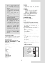
5.4 Leak Detection
5.5 Heat Insulation
Electronic leak detectors shall be used to check whether
air leaks at each joint.
A and B indicate check valves of ODU.
C and D indicate IDU connecting pipe ports.
All of the connection ports between the branch
header and refrigerant pipe.
Figure 5-7
IDU check point
ODU check point
B
A
D
C
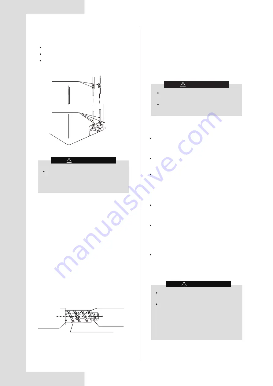
Carry out heat insulation treatment for the pipes at the
gas and liquid sides respectively. Pipes on the liquid and
gas sides have a low temperature during cooling. Take
sufficient insulation measures to prevent condensation
(see Figure 5-8).
The gas pipe must be treated with the closed-cell foam
insulation material, which is rated at a non-flammable
level of B1 and heat resistance of over 120°C.
When the outer diameter of the copper pipe is not greater
than Φ12.7 mm, the thickness of insulation layer should
be greater than 15mm.
When the outer diameter of the copper pipe is equal to or
greater than Φ15.9 mm, the thickness of the insulation
layer should be greater than 20 mm.
The attached insulation material for the part of the IDU
where the pipe connects must undergo heat insulation
treatment without gaps.
Figure 5-8
The unit body
Affiliated heat pump belt
Site pipe side
Cut from upward
WARNING
During the maintenance process, it is necessary
to enter the vacuum mode when vacuumizing.
If the system is configured with a refrigerant
shut-off device, vacuuming needs to be done
from the maintenance needle valves of the ODU
check valves and the refrigerant shut-off device
separately. In additional, only vacuuming from
the ODU is also allowed when the system is
powered on and the ODU is without any error
code of Ad1, C21, C26, C28, C2A and EC1.


