background image

1 Introduction

FOCUS

11

1.10 Disposal

When  the  unit  does  no  longer  meet  the  manufacturer's
intended  operational  specifications,  despite  proper
maintenance  and  repair,  then  the  unit  is  no  longer
serviceable and should be replaced. Follow all regulations
on  disposal  of  waste  parts.  The  unit  has  at  least  the
following  parts  that  should  be  regarded  as  non-
environmentally friendly waste products:

- X-ray source assembly

- All electronic circuits

Summary of Contents for FOCUS

Page 1: ...FOCUS Intraoral X ray User Manual ENGLISH 214760 rev 3 0 805 4936...

Page 2: ......

Page 3: ...ntation may not be copied photocopied reproduced translated or reduced to any electronic medium or machine readable form in whole or part without the prior written permission of Instrumentarium Dental...

Page 4: ......

Page 5: ...tionary actions for safe use 17 3 2 Switching the power on off 17 3 3 Selecting the cone 18 3 4 Selecting the exposure parameters 18 3 5 Positioning the patient 20 3 6 Taking an exposure 22 3 7 Monito...

Page 6: ...ii...

Page 7: ...settings can be reprogrammed if needed Other user settings include selecting 60 or 70 kV setting exposure times between 0 02 and 3 2 seconds and pediatric or adult modes Exposures can be made directl...

Page 8: ...oduction 2 FOCUS 1 3 User profile The unit is intended only for professionally qualified dental or medicinal personnel The typical user is a dental nurse with specific training for using dental X ray...

Page 9: ...llowing symbols are used in the unit Name and address of the manufacturer Serial number X ray source assembly emitting Radiation warning Radiation generating unit Focal spot Filtration Connector for r...

Page 10: ...nsed healthcare practitioner Do not reuse Recyclable Stacking limit Max 4 transportation packages may be vertically stacked CE 0537 symbol MDD 93 42 EEC ETL Mark Conforms to UL STD 60601 1 Certified t...

Page 11: ...under side of the horizontal arm and in the tube HV generator housing assembly label on the tube head The unit is class I type B and with IP 20 protection The focal length is defined in the cone label...

Page 12: ...1 Introduction 6 FOCUS 1 6 Labels on the unit Labels on the picture are for reference purposes only Actual texts may not be accurate...

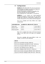
Page 13: ...unit is available with three different arm length configurations Each unit is equipped with remote control with 32 8 feet 10m 8 wire cable with RJ 45 plugs and Installation manual The unit is availab...

Page 14: ...ount plate ACCESSORIES Short cone round SSD 229 mm 9 60 mm Short cone rectangular small SSD 229 mm 9 28x36 mm Short cone rectangular SSD 229 mm 9 35x45 mm Long cone round SSD 305 mm 12 60 mm Long cone...

Page 15: ...mmended to provide the patient with a protective apron Consult the physician before taking images of pregnant patients WARNING The unit must not be used in rooms where explosive hazards exist Use the...

Page 16: ...ntraoral x ray dental dealer Original or authorized spare parts are used If service on the unit is performed a work order describing the type and extent of repair must be provided by the service techn...

Page 17: ...ications despite proper maintenance and repair then the unit is no longer serviceable and should be replaced Follow all regulations on disposal of waste parts The unit has at least the following parts...

Page 18: ...parts 1 Mounting system Options Narrow wall mount default Wide wall mount Adapter for KaVo treatment units 2 Connection box Mains wiring 3 Horizontal arm Options Short reach Medium reach Extra long r...

Page 19: ...one rectangular Long cone round Long cone rectangular Short cone full metal rectangular Long cone full metal rectangular 7 Remote control panel Includes a 10m cable and exposure button on the control...

Page 20: ...2 Unit description 14 FOCUS Long cone rectangular SSD 305 mm 12 35x45 mm Short cone full metal rectangular SSD 229 mm 9 35x45 mm Long cone full metal rectangular SSD 305 mm 12 35x45 mm...

Page 21: ...cuspid Maxillary incisors Bitewing Mandibular molar Mandibular cuspid Mandibular incisors Occlusal Exposure button X ray source assembly emitting Ready for exposure Patient Size Selection Digital mode...

Page 22: ...2 Unit description 16 FOCUS Exposure time control...

Page 23: ...exposed electrical connectors simultaneously 3 2 Switching the power on off The power switch is located on the bottom of the access block Turn the switch to the ON I position to switch the unit on The...

Page 24: ...it and pulling it out Then push and rotate the new cone in NOTICE Make sure that the values set in the programming mode correspond to the cone length and shape 3 4 Selecting the exposure parameters 1...

Page 25: ...h button light indicators will be off 5 The exposure time may be adjusted manually with the UP and DOWN buttons The exposure time is based on the tooth type patient size exposure mode film or digital...

Page 26: ...towards the film sensor observing the correct angle of the beam The horizontal angle of the cone is indicated on the scale located around the vertical joint of the tube head NOTICE Always use disposa...

Page 27: ...4 Instruct the patient to avoid any movement during the exposures WARNING Take care not to hit the patient with the unit during the positioning of the patient NOTICE If the resulting image isn t adequ...

Page 28: ...g the exposure and will reflect the elapsed time of the actual exposure afterwards NOTICE When using the system in an extremely high electromagnetic environment interferences may change image quality...

Page 29: ...display will show the updated exposure time Menu Selections Display Contents Film Speed Pr1 fast film Speed F SF fast film Ekta speed E SE slow film Ultra speed D Sd Cone selection Pr2 short round 1...

Page 30: ...en preprogrammed by the factory but can be changed if necessary by the user First increase or decrease the exposure time with UP and DOWN buttons Then press and hold the corresponding tooth button for...

Page 31: ...Contact the service E4 Tube head too hot or too cold Wait for valid tube head temperature E5 Line voltage low Contact the service E6 not in use N A Contact the service E7 EEPROM failure Contact the se...

Page 32: ...5 Error messages 26 FOCUS...

Page 33: ...n and thus facilitate the removal of protein substances Then wipe with a cloth moistened in clear water Mild detergent solution can be used Never use solvents of any kind If you are uncertain of the n...

Page 34: ...diately reported to your dealer WARNING Only trained and qualified personnel should be permitted to access the internal parts of the unit CAUTION After the operation in the service mode the unit must...

Page 35: ...ation detector not supplied with the unit on the test object and position the cone of the unit on the radiation detector Recommended technique factors for conducting this test are 70 kV 0 2s exposure...

Page 36: ...fuse base and twist it counterclockwise with a screwdriver The fuse with the base will come out Remove the fuse from the base and replace it with the new one Repeat this with each blown fuse Fasten bo...

Page 37: ...dels marked according to the Medical Device Directive 93 42 EEC Product Name FOCUS intraoral x ray Type FOCUS UNIT DATA Protection against electric shock Class I Degree of protection Type B Protection...

Page 38: ...mm according to IEC 60336 2005 Nominal anode input power 940 W Max symmetrical radiation field 60 mm at a 200 mm focal length Total filtration 2 0 mm Al 70 kV Inherent filtration 1 mm Al 70 kV Fixed...

Page 39: ...allation Standard wall mount Optional base for free standing unit Height x Width x Depth mm Unit 1059 mm x 279 mm x 946 1096 1346 mm Tube head assembly 112 mm x 260 mm x 201 mm Weight Unit approximate...

Page 40: ...1 69 7 29 4 38 9 29 0 38 9 16 4 21 7 0 400 65 2 87 4 36 7 48 9 36 3 48 7 20 5 27 2 0 500 81 7 109 7 45 9 61 1 45 5 61 1 25 6 34 1 0 630 103 0 138 1 57 8 77 1 57 4 76 9 32 2 42 9 0 800 130 7 175 5 73 2...

Page 41: ...observed such as degradation of essential performance in form of reduction of line pair resolution additional measures may be necessary such as re orienting or relocating the device The device is suit...

Page 42: ...ny interference in nearby electronic equipment Radio Frequency Emissions CISPR11 Class B The device is suitable for use in both at professional healthcare hospitals large clinics facility environment...

Page 43: ...l mode 0 5 1 2 kV common mode 0 5 1 kV differential mode 0 5 1 2 kV common mode Mains power quality is that of a typical commercial and or hospital environment Voltage dips short interruptions and vol...

Page 44: ...he device including cables than the recommended separation distance calculated from the equation appropriate for the frequency of the transmitter Recommended Separation Distance 150kHz 80MHz 80MHz to...

Page 45: ...cating the device Guidance for actions taken can be found from AAMI TIR 18 2010 Guidance on electromagnetic compatibility of medical devices in healthcare facilities NOTICE Precautions to take if the...

Page 46: ...tput Power of Transmitter watts 150 kHz to 80 MHz Separation Distance meters 80 MHz to 800 MHz Separation Distance meters 800 MHz to 2 7 GHz Separation Distance meters 0 01 0 20 0 06 0 06 0 1 0 63 0 1...

Page 47: ...s In order to reduce electrostatic discharge interference a charge dissipative floor should be installed to prevent charge accumulation The dissipative floor material must be connected to the system r...

Page 48: ...7 Technical data 42 FOCUS...

Page 49: ...ge is 70 kVp Nominal focal spot is 0 7 mm X ray tube D 0711SB or D 0711S For additional information please refer to the tube specification sheets Art No Part number Cones Program Mode Pr2 Cone type ID...

Page 50: ...it shall not be placed on the floor WARNING Multiple extension cables shall not be used WARNING The x ray unit must be connected to it s own separate power supply PC or any other external units must N...

Page 51: ...8 User s statement FOCUS 45 TUBE RATINGS TUBE HEAD COOLING CURVE Fig 8 1 Maximum Rating Chart D 0711SB or D 0711S...

Page 52: ...8 User s statement 46 FOCUS Fig 8 2 Tube anode thermal characteristics D 0711SB or D 0711S TUBE HEAD THERMAL CHARACTERISTICS Fig 8 3 Tube head assembly cooling curve...

Page 53: ...TUBEHEAD Fig 8 4 Tubehead dimensions and the location of the focal spot Exp time Wait time Exp time Wait time 0 02s 10s 0 32s 10s 0 03s 10s 0 40s 10s 0 04s 10s 0 50s 10s 0 05s 10s 0 63s 19s 0 06s 10s...

Page 54: ...alue measured over the high voltage feedback resistor with a calibrated voltage device mA The tube current mean value calculated by dividing the voltage over the feedback resistor value The voltage is...

Page 55: ...0 080 0 250 0 160 Maxillary molar 0 320 0 200 0 500 0 400 0 160 0 100 0 320 0 200 Occlusal 0 250 0 160 0 500 0 320 0 125 0 080 0 250 0 160 Mandibular incisor 0 200 0 125 0 400 0 250 0 100 0 063 0 200...

Page 56: ...9 Recommended exposure times 50 FOCUS...

Page 57: ...presentative for the most current information Copyright by PaloDEx Group Oy All rights reserved 216457 3 Headquarters PaloDEx Group Oy Nahkelantie 160 FI 04300 Tuusula FINLAND Tel 358 10 270 2000 http...

Reviews: