8
Electric Dispenser Hoist EWL 2, 3, 4
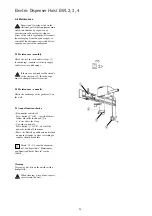
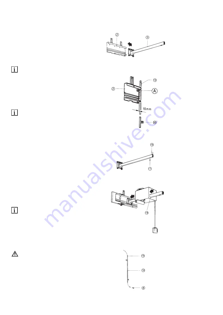
A 5.4 Mounting the load arm
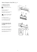
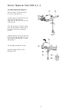
Insert the load arm
3
into the guide rail
2
at the side.
Screw the protective tube
0
with the
guide rail
2
(hole A) to the wall.
Please observe the minimum dis-
tance of 10 mm to the outer edge of
the guide rail
2
.
Align the protective tube
0
vertically, drill
the lower securing point
ö
and screw to
the wall.
The protective tube
0
is a safety
limit stop against accidental with-
drawal of the load arm
3
.
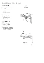
A 5.5 Mounting the carriage
1
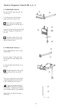
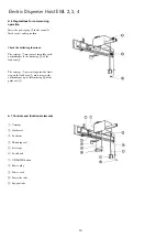
Unscrew rubber buffer
u
and screws
z
on load arm
3
.
Move the carriage
1
with groove
i
in
the direction of the arrow along the load
arm
3
.
Screw on the rubber buffer
u
and screws
z
again.
The rubber buffer
u
and screws
z
are limit and safety stops for the
carriage.
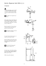
Unscrew screws
o
on protective tube
0
and pull through the power cord until the
nearest socket outlet can be reached.
Work on the electrical part of the
equipment may only be carried out
by specialists or staff trained in the factory,
who are familiar with the safety regulations!
Connect the power plug
8
according to
regulations.


