Instructions for use ESTETICA E70 Vision / E80 Vision
8 Appendix - Additional measuring sites | 8.1 Additional scanning sites SL X in the protective conductor measure-
ment
8 Appendix - Additional measuring sites
Note
With reference to accessories, which are not listed here, the specifications of
the relevant instructions for use must be observed. Example: ERGOcam 5.
8.1 Additional scanning sites SL X in the protective
conductor measurement
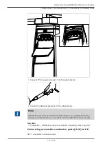
ERGOcam One module
①
Screw in bottom part of housing
Note
The modules are not earthed with a safety conductor. In the case of excess-
ive PE resistance, the electrical connection between the module and the dent-
ist element must be improved. This can be accomplished, for example, by
means of a serrated lock washer on the fastening screw.
Connector for third-party equipment
▶
Position the test tip on the middle contact
①
.
167 / 178
Summary of Contents for ESTETICA E70 Vision
Page 1: ...Instructions for use ESTETICA E70 Vision E80 Vision...
Page 177: ......
Page 178: ...1 012 5446 Fk 20191030 9 en...


