background image

Instructions for use MASTERsurg LUX Wireless REF 1.009.1200

7 Reprocessing steps in accordance with DIN EN ISO 17664 | 7.2 Disinfection

60 / 76

7.1.2 Machine cleaning

 CAUTION

Damage by liquids.
Faults on electrical components.

▶ Do not machine-clean the device.

The following parts of the unit are released for machine-based cleaning:

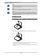
▪ Handpiece tray

▪ Motor and motor cable

Note

Please comply with the corresponding Instructions for use when you re-process the
motor and motor cable.

The re-processing steps for the handpiece tray are as follows:

KaVo recommends washer disinfectors in compliance with EN ISO 15883-1 that are
operated with alkaline cleaning agents.
The validations were conducted with the VARIO-TD program, the cleaning agent
neodisher® MediClean and the neutralisation agent neodisher® Z.

▶ For program settings as well as cleansers and disinfectants to be used, please

refer to the Instructions for Use of the thermodisinfector.

7.2 Disinfection

Note

After each treatment of a patient, the surfaces near the patient that may have been
contaminated by contact or aerosol need to be disinfected. All disinfection meas-
ures need to be carried out by wipe disinfection.

Note

Please comply with the corresponding Instructions for use when you re-process the
motor and motor cable.

7.2.1 Manual disinfection

▶ Use a soft disposable cloth and an approved disinfectant for disinfection by wiping

down all visible surfaces of the unit, bottle holder, wireless foot control surfaces,
and connecting cables. Make sure that all surfaces are wetted.

▶ Let the disinfectant act for the prescribed time.

▶ Dry the surfaces.

Permissible disinfectants (application range in accordance with the available manufac-
turer's instructions and national guidelines. Please note material safety data sheets.)
KaVo recommends the following products based on the compatibility of the materials.
The microbiological efficacy must be confirmed by the disinfectant manufacturer.

▪ FD 322 Dürr

▪ Microcide AF Liquid (Schülke & Mayr)

▪ CaviCide made by Metrex

Summary of Contents for 1.009.1200

Page 1: ...Instructions for use MASTERsurg LUX Wireless REF 1 009 1200...

Page 2: ...Distributed by KaVo Dental GmbH Bismarckring 39 D 88400 Biberach Phone 49 7351 56 0 Fax 49 7351 56 1488 Manufacturer Kaltenbach Voigt GmbH Bismarckring 39 D 88400 Biberach www kavo com...

Page 3: ...4 Wireless foot control 17 3 5 Rating plates of MASTERsurg LUX Wireless and wireless foot control 17 3 6 Technical Specifications MASTERsurg LUX Wireless 19 3 7 Scope of delivery 20 4 Commissioning 21...

Page 4: ...ant flow 46 5 6 4 Changing the direction of motor rotation 47 5 6 5 Setting the transmission ratio 48 5 7 Rinsing function 48 5 7 1 Manual rinsing function 48 5 7 2 Program activity rinsing function 4...

Page 5: ...tic compatibility 70 12 1 Guidelines and manufacturer s declaration electromagnetic emission 70 12 2 Guidelines and manufacturer s statement Electromagnetic immunity 70 12 3 Guidelines and manufacture...

Page 6: ...ment is for dentists and dental office staff 1 3 Service Please direct all questions regarding the product service and maintenance to the fol lowing addresses Please refer to the serial number of the...

Page 7: ...bulbs glassware rubber parts and the colour fastness of plastics Defects or their consequences that can be attributed to interventions on or changes made to the product by the customer or a third part...

Page 8: ...delivery re ceipt The recipient and the representative of the shipping company must sign this delivery receipt Without this evidence the recipient will not be able to assert a claim for damages agains...

Page 9: ...Instructions for use MASTERsurg LUX Wireless REF 1 009 1200 1 User instructions 1 5 Transportation and storage Permissible stacking load Temperature range Humidity Air pressure 9 76...

Page 10: ...at can cause damage to property or mild to moder ate injuries WARNING WARNING indicates a hazardous situation that can lead to serious or fatal injury DANGER DANGER indicates a maximal hazard due to a...

Page 11: ...3304 3919 590 to enretec GmbH The following contact options are also available for questions and for initiating a disposal order Phone 49 0 3304 3919 500 Email eom enretec de and Postal address enret...

Page 12: ...duct in a tub like container Check the coolant containers and lines for absence of leakage If any liquid is de tected on the device do not touch the device and disconnect the device from the mains sup...

Page 13: ...wing Applicable regulations governing the connection and start up of medical devices Current occupational safety regulations Current accident prevention regulations It is a responsibility of the user...

Page 14: ...sed of in strict compliance with all applicable national regulations in a manner which is safe both for people and the environment If you have any questions regarding proper disposal of the KaVo produ...

Page 15: ...Wireless REF 1 009 1200 3 Description of the product 3 2 MASTERsurg LUX Wireless Rear 3 2 1 5 4 6 Hose pump locking mechanism On button Power plug Please note the instructions for use Follow the inst...

Page 16: ...isplay of the activity Maximal torque reached Torque limit Speed Wireless foot control status indicator input implant position Activation of one touch calibration Coolant pump settings Direction of mo...

Page 17: ...Direction of motor rotation key yellow 3 5 Rating plates of MASTERsurg LUX Wireless and wireless foot control The rating plates of MASTERsurg LUX Wireless and wireless foot control are affixed on the...

Page 18: ...ontrol 18 76 Follow the instructions for use Operating mode continuous operation with intermittent load Alternating current AC Supply voltage Protection class II Manufacturer YYYY Year manufactured XX...

Page 19: ...ontrol Class of protection IPX8 Wireless foot control Emitted power max 3 dBm e i r p Wireless foot control Frequency band ISM 2 4 GHz Length of motor cable 6 5 ft 2 m Operating mode Continuous operat...

Page 20: ...livery The scope of delivery of the MASTERsurg LUX Wireless includes the following MASTERsurg LUX Wireless unit Wireless foot control Surgical motor INTRA LUX S600 LED Motor cable S600 Instrument tray...

Page 21: ...ess foot control and additional equipment To take out the unit pull it vertically upward and place it on a level surface 4 2 Installing the bottle holder Slide the bottle holder in the guide on the un...

Page 22: ...bar including the pump button program button and motor direc tion button slightly upwards and take it off the wireless foot control To open the lid turn it to the left and take it off Insert 3 batter...

Page 23: ...ignated recesses The wireless foot control is now ready for operation and can be used The initial con nection is done at the factory Note Stand by mode The wireless foot control does not need to be sw...

Page 24: ...dance with DIN EN ISO 17664 Page 58 1 2 3 4 Motor coupling Surgical motor Handpiece tray Plug of motor cable Plug the surgical motor into the motor coupling and secure it with a union nut Please note...

Page 25: ...e of 1 litre only Check the stability Note The coolant must be selected to suit the planned application The flow rate of the coolant is dependent on the instrument used The user must set an adequate f...

Page 26: ...ess REF 1 009 1200 4 Commissioning 4 5 Connecting the coolant container and hose set 26 76 ca 10 mm Coolant hose Clips Hose fixation Lock Pump hose Insertion needle Hose clamp Coolant hose Clip Hose f...

Page 27: ...coolant hose tightly without loops or kinks against the outside of the motor cable and attach it in regular intervals using the enclosed clips Plug the hose fixation into the opening of the device wi...

Page 28: ...cting the coolant container and hose set 28 76 ca 10 mm Open the lock and insert the pump hose Close the lock Note Make sure to place the pump hose in the pump appropriately such that the pump hose do...

Page 29: ...a glass bottle open the ventilation on the puncture needle If you use a bag keep the ventilation on the puncture needle closed Open the hose clamp before startup Note Using a new hose it may take up...

Page 30: ...riately such that the mains plug and the electrical outlet are easily accessible Note The protective earth conductor is used as functional earthing FE rather than as protective earthing PE Plug the ma...

Page 31: ...ght on the handpiece the pump and the motor on the unit are turned off 5 2 Device settings The following device settings can be made or displayed Setting the language Setting the documentation Setting...

Page 32: ...5 2 2 Setting the documentation Three modes are available Implant Documentation during implant insertion Permanent Documentation of entire treatment process on SD card Off Documentation disabled Touch...

Page 33: ...fterglow 5 2 5 Setting the operating mode of the foot pedal The motor can be triggered in either of two operating modes The motor starts at full speed when the foot pedal is actuated The motor speed c...

Page 34: ...d wireless foot control communicate these need to be connected The wireless foot control can be connected in three steps 1 Touch the symbol to start the connection process 2 Press and hold down the sp...

Page 35: ...ge the date 5 2 10 Setting the LCD brightness The LCD brightness determines the brightness of the display The brightness can be set in 3 steps ranging from dark to maximal brightness Press the plus an...

Page 36: ...able After start up you can start immediately with the first step of treatment Multiple programs After start up an overview of the 10 programs is displayed For each program up to 4 to 10 program steps...

Page 37: ...store the factory settings In the window you will be asked whether or not you wish to carry out the action Touch Yes to carry out the action Press No or the back key to discontinue the action 5 2 17 V...

Page 38: ...Following instructions for use service instructions and installation instructions in the motor handpiece and contra angle handpiece packaging All straight and contra angle handpieces with INTRAmatic...

Page 39: ...ght or contra angle handpiece slightly to pull it off 5 4 Setting up multi program mode A total of 10 programs are available to the user These can be assigned e g to vari ous users or implant systems...

Page 40: ...ns mission ratios and coolant flow rate for every activity according to application The parameters can be changed only within a reasonable range for the specific activity In the activity Free applicat...

Page 41: ...im plant 15 50 20 D 5 80 25 D 16 1 27 1 20 1 D 0 4 0 D 6 Setting a clos ure cap 15 50 20 D 5 15 8 D 16 1 27 1 20 1 D 0 4 0 D 7 Free use 300 40 000 40 000 D 0 15 5 5 3 D 1 1 0 4 2 D 20 2 000 5 80 16 1...

Page 42: ...ted can be set from pro gram step 4 Symbol Example 2 Program steps that do not include the activity Cut thread and include the Rinsing function activity Step 1 2 3 5 4 5 7 Activity Marking Pilot drill...

Page 43: ...ogram step is saved automatically The program steps can be selected during the treatment using the program key of the wireless foot control After the last program step follows the first step again Pre...

Page 44: ...ouch the activity display Select the flag symbol The settings are saved automatically and the treatment is terminated with the selected program step Navigating through the program steps with the wirel...

Page 45: ...h the plus or minus area The value is saved automatically Press the back key to close the speed setting 5 6 2 Setting the torque limit Note The MASTERsurg LUX Wireless reduces the power to prevent the...

Page 46: ...displayed during the treatment in the activities Cut thread Place implant and Set closure cap The value is re set as soon as the motor starts again 5 6 3 Setting the coolant flow CAUTION Coolant dosed...

Page 47: ...g the treatment using the pump key of the wireless foot control The pump key has two operating modes See also 2 5 2 6 Setting the operating mode of the pump key of the foot control Page 33 The changed...

Page 48: ...5 11 Wireless foot control Page 52 Three audible signals indicate counterclockwise rotation When the motor starts up 3 more audible signals are issued Note The set torque automatically increases by 5...

Page 49: ...e speed key on the wireless foot control to start the rinsing function and control the coolant flow To terminate the rinsing function press the back key or the pump key 5 7 2 Program activity rinsing...

Page 50: ...atios The calibration must be repeated whenever the handpiece is changed Touch the calibration symbol in order to start the One Touch calibration The display shows Press wireless foot control CAUTION...

Page 51: ...rection of rotation program name implant position activity transmis sion ratio pump level software version and serial number of the unit to be recorded Three modes are available Implant A torque plot...

Page 52: ...s on the wireless foot con trol or by touching the back key on the unit The updated torque plot is displayed again after each motor stop 5 11 Wireless foot control 5 11 1 Changing the speed coolant fl...

Page 53: ...of the wireless foot control Press the program key of the wireless foot control briefly to select the next pro gram step Press the program key of the wireless foot control long to select the previous...

Page 54: ...al connection Turn the device off Disconnect the power cable the socket of the supply mains Disconnect the power cable from the device 6 2 Disposal of the coolant hose Note The coolant hose with acces...

Page 55: ...ing the surgical motor Disconnect the plug of the motor cable from the connector on the device Make sure to grasp the plug as close to the device as possible Note Cleaning and disinfecting the motor c...

Page 56: ...speed button off the wireless foot control 1 Pull the button bar including the pump button program button and motor direc tion button slightly upwards and take it off the wireless foot control Turn t...

Page 57: ...4 Plug the speed button onto the wireless foot control and press it on lightly until the snap in lug snaps in Make sure that the foot pedal springs are situated in the recesses of the housing 6 5 Dism...

Page 58: ...structions for cleaning and sterilisation have been validated by the manufac turer Any departure from the instructions provided must be checked by the user for efficacy and possible detrimental conseq...

Page 59: ...l parts of the wireless foot control under running water and then dry them 1 2 2 2 2 3 Plug the button bar onto the wireless foot control and press it on lightly until the button bar snaps into place...

Page 60: ...Use of the thermodisinfector 7 2 Disinfection Note After each treatment of a patient the surfaces near the patient that may have been contaminated by contact or aerosol need to be disinfected All dis...

Page 61: ...with accessories is intended for single use only and is not to be disin fected and sterilised No drying required Allow all disinfected and and sterilised parts to dry fully on room air before using t...

Page 62: ...er sterilising and drying Note Treating patients who are possibly afflicted by an acute critical infectious disease be sure to comply with the hygienic measures cited in applicable publications and re...

Page 63: ...s at 134 C 1 C 4 C 273 F 1 6 F 7 4 F Drying time 30 min Note Allow the sterilised items to cool to room temperature before using them again 7 4 1 Storage Observe all necessary measures for hygiene whe...

Page 64: ...he coolant flow Page 46 Hose fixation is not plugged in Plug in the hose fixation See also 2 4 5 Connecting the coolant container and hose set Page 24 Bottle is empty Connect new bottle Hose clamp is...

Page 65: ...e engineer Event E6 Internal communication er ror Internal system error Turn the unit off and on If the problem persists notify service engineer Event E9 Setting the time and date Time was not reset a...

Page 66: ...erform a run in the absence of the straight or con tra angle handpiece If no error message is displayed the handpiece runs too sluggish Use a different straight or contra angle handpiece If the run in...

Page 67: ...the bin file extension the downloaded current file is stored on the SD card Turn the device on The update process starts automatically Note The unit must not be turned off during the update process Af...

Page 68: ...bol Description green Service check is soon due Arrange a precautionary appointment at a KaVo subsidiary or with a KaVo authorised dealer yellow Service check is due Arrange an appointment at a KaVo s...

Page 69: ...Wireless Hose set sterile S600 10 pcs Mat no 1 009 8757 Hose set sterilisable S600 Mat no 1 011 0633 Handpiece tray Mat no 1 009 3411 Motor INTRA LUX S600 LED Mat no 1 008 8000 Motor cable S600 Mat no...

Page 70: ...cted to a public power supply that also sup plies residential buildings Emission of harmonics according to IEC 61000 3 2 Class A The MASTERsurg LUX Wireless is intended for use in all facilities in cl...

Page 71: ...environment Voltage interruptions short term interruptions and fluctuations of the sup ply voltage according to IEC 61000 4 11 5 UT for 1 2 period 95 interruption 40 UT for 5 periods 60 interruption...

Page 72: ...80 MHz and 800 MHz the higher frequency range applies Note 2 These guidelines may not be applicable in every case The propagation of electromagnetic waves is subject to absorption and reflection by b...

Page 73: ...1 17 2 33 10 3 70 3 70 7 37 100 11 70 11 70 23 30 For transmitters whose maximum rated power is not included in the above table the recommended safe distance d in metres m can be calculated using the...

Page 74: ......

Page 75: ......

Page 76: ...1 010 3594 bd 20161206 04 en...

Reviews: