Kato IC120-2 Operation Manual Download Page 102

MAINTENANCE 

IC120-2 ENG 

4-24 

IC120-2-C401160

1

2

3

5

IC120-2-C401170

4

6

Change the Coolant 

Replace coolant every 2000 years or once every two years. 
Use solution of 50% water and 50% ethylene glycol long life coolant (LLC) and DCA solution as 
coolant.  Never use water only as coolant. 

 
Pouring quantity when replacing coolant 

Total coolant quantity 

36.5 L 

Engine body:  12.8 L 
Radiator, etc.:  13.6 L 
Coolant tank:  10.2 L 

Mixture of LLC and water 

34.6 L 

LLC = 17.3 L 
Water = 17.3 L 


  Immediately after the engine stops, coolant is 

hot.  If coolant is discharged immediately, you 
may get burnt.  Change coolant after the engine 
cools down. 

  Do not remove the cap when the radiator 

coolant is hot.  Hot water may spout out. 
Rotate the cap slowly to relief the pressure after 
the coolant temperature lowers. 

 
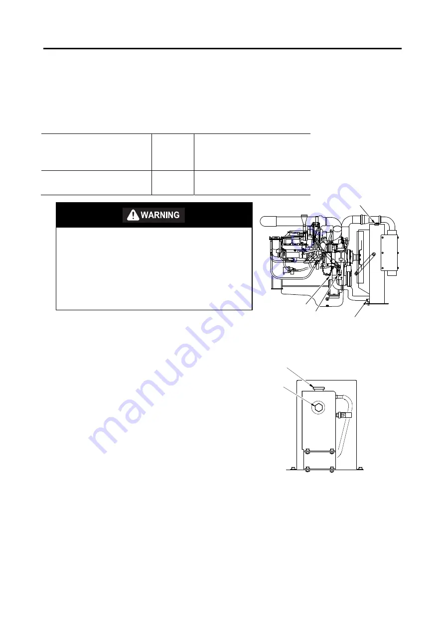
1.  Slowly turn the pressure cap (4) on the coolant tank to 

remove it. 

2.  Loosen the drain cock (2) in the lower part of the 

radiator and discharge water into a vessel. 

3.  Loosen the drain cock (3) of the cylinder block of the 

engine and discharge water into the vessel. 

4.  Loosen the drain cock (5) of the coolant tank and 

discharge water into the vessel. 

5.  Turn the radiator cap (1) slowly to remove it.  
6.  Clean the coolant tank. 
7.  Close the drain cocks (2), (3) and (5) after discharging 

water. 

8.  Pour fresh LLC mixture and DCA solution through the 

radiator cap.  Keep the pressure cap of the coolant 
tank removed at this time.  Make sure that the tank 
becomes full, and close the radiator cap. 

9.  Pour fresh LLC mixture into the coolant tank.  Check 

the level through the sight glass (6) of the coolant tank 
and close the pressure cap then. 

10.  Run the engine five minutes and stop it then.  Wait 

until the temperature of coolant lowers, and check the 
coolant level.  Refill the tank with coolant if coolant is 
insufficient. 

Coolant tank 

Summary of Contents for IC120-2

Page 1: ...IC120 2 CB004001 IC120 2 0988477EN 00 0988477EN 00...

Page 2: ...on of Screen Displays 2 5 Trouble Code Display Screen 2 8 Regeneration Mode Selection Screen 2 10 Machine Information Display Screen 2 10 Adjustment Selection Display Screen 2 11 Safety Warning Device...

Page 3: ...ose 4 3 Hydraulic Hose 4 3 SCR Piping Hose 4 3 MAINTENANCE INTERVALS 4 4 RECOMMENDED LUBRICATION TABLE 4 6 GREASING 4 7 Vessel 4 7 Oscillating Link 4 7 RUBBER CRAWLER 4 8 Rubber Crawler Shoe Maintenan...

Page 4: ...ent of DEF 4 27 FUEL SYSTEM 4 28 Applicable Fuel 4 28 Check the Fuel Level 4 29 Drain the Fuel Tank 4 29 Water Separator and Fuel Filter 4 30 Replacing Water Separator and Fuel Filter 4 31 AIR INTAKE...

Page 5: ...be thoroughly understood at first repeat reading it until abilities as an operator are obtained and developed for proper operation Further abilities as an operator outside of descriptions in this manu...

Page 6: ...injury This safety alert symbol and signal word indicates a potentially hazardous situation which if not avoided could result in death or serious injury This safety alert symbol and signal word indic...

Page 7: ...eglected or basic safety instructions are not observed Such accidents may be avoided by paying careful attention in advance This manual describes the basic safety instructions to be observed in daily...

Page 8: ...ol medication or intoxication WEAR PROPER WORKING CLOTHES For the sake of safety during driving wear clothes that match your body The sleeves of sloppy clothes can get caught in the machine and can ca...

Page 9: ...he operator s station When any oil or other slippery substance has got adhered to hand rails or steps wipe them off clean START THE ENGINE WHILE SITTING IN THE OPERATOR SEAT If the engine is started f...

Page 10: ...engine in a well ventilated area If in an enclosed area vent the exhaust to the outside STAY SEATED WHILE OPERATING There is the danger of making wrong operations if the operating is done from a posi...

Page 11: ...e a load onto the sideracks DO NOT EXCEED THE WATER DEPTH LIMIT The acceptable water limit is up to the lower roller Check the water depth foundation and strength of water current and other safety fac...

Page 12: ...HINE POSITION WHILE TRAVELING ON SLOPES The machine center of gravity tends to quickly change while traveling on sloping surfaces This can create hazardous situations where the machine may tip over Ob...

Page 13: ...arked on a sloping land When it is unavoidable to stop or park on a slopping land Place stopper blocks on the downhill side under both crawlers OBSERVE PRECAUTIONS WHEN PARKING THE MACHINE ON THE ROAD...

Page 14: ...he machine to the platform using a wire rope etc Transport safely strictly following the concerned laws PRECAUTIONS AT MAINTENANCE KEEP ROUTINE MAINTENANCE Wrong maintenance not only causes damage to...

Page 15: ...fter completely releasing the internal pressure SUPPORTING THE VESSEL If replacement or repair of couplings or hoses is made with the vessel in the raised condition there is the possibility that the v...

Page 16: ...ushed by the machine and there is the danger of your hand being cut off Always carry out maintenance work with the engine switched off BE CAREFUL TO HOT ENGINE AFTER THE MACHINE STOPS Do not touch the...

Page 17: ...g used for the battery liquid Take sufficient care while handling FIRE PREVENTION Do not leave burnable items such as oily rags dry leaves paper etc near the engine Since these can cause fire hazards...

Page 18: ...ead the words Check the part number for the safety sign against this manual or the actual object before placing an order Where the warning Signs and Labels are stuck IC120 2 C101000 A 11 18 15 21 12 1...

Page 19: ...20 2 ENG 1 12 1 Precautions on safety D408 704 00 2 Precaution for working under the raised vessel 4448 816 00 3 Crawler shoe tension adjustment D405 516 00 4 How to lower body in case of emergency D4...

Page 20: ...1 13 5 Gate lock lever D408 689 00 6 Traveling on a slope D406 188 00 7 Loading and unloading the machine D405 618 00 8 Under water works D406 189 00 9 Safety alarm D408 691 00 10 Dump bed operation w...

Page 21: ...r touch when hot D405 477 00 14 Sign indicates an electrical hazard from handling the cable Read manual for safe and proper handling D405 363 00 15 Sign indicates an electrocution hazard if machine is...

Page 22: ...he machine to minimize danger caused by accidents such as falling down D407 774 00 22 Sign indicates a crush hazard from falling vessel Read manual and follow safety instructions when holding the vess...

Page 23: ...SAFETY IC120 2 ENG 1 16 25 Contains Fluorinated Greenhouse Gases Only for air conditioner equipped machine D409 001 00...

Page 24: ...IC120 2 ENG CONTROLS This section describes the functions of the devices needed to operate this machine and the proper operation procedures Understand them sufficiently and operate the machine in safe...

Page 25: ...er roller 2 Fuel tank 10 Dump cylinder 18 Oscillating link 3 Hydraulic tank 11 Safety bar 19 Travel device 4 Engine 12 Vessel 20 Drive sprocket 5 Radiator oil cooler 13 Rear gate 21 Headlight 6 Post p...

Page 26: ...CONTROLS IC120 2 ENG 2 2 CONTROLS AND INSTRUMENTS No Name No Name 1 Instrument panel 4 Operator seat 2 Left lever unit 5 Seat belt 3 Accelerator pedal...

Page 27: ...ghter 24 V 2 Travel speed select switch 9 Emergency engine stop switch 3 Parking switch 10 Engine service connector 4 Mode changeover switch 11 Engine key switch 5 Engine speed control dial 12 Hour me...

Page 28: ...the Operation screen when the key is pressed The initial screen appears when the engine key switch is turned to the ON position The initial screen changes to the Operation screen in 3 seconds Initial...

Page 29: ...Engine tachometer 2 Coolant thermometer 3 DEF gauge 4 Fuel gauge 5 Battery voltage 6 Slope warning indicator 7 Preheat indicator 8 High speed 9 Low speed 10 Parking brake indicator 11 Engine error ind...

Page 30: ...inclination angle is 9 degrees or more the buzzer sounds for 5 seconds 7 Preheat indicator The preheat indicator comes on when the engine key switch is turned on The water temperature sensor senses th...

Page 31: ...ator This indicator comes on when some kind of engine problem occurs When an engine error is indicated immediately contact our service dealer 12 DEF indicator This indicator comes on when the DEF Dies...

Page 32: ...flashes move to a safe area and stop the engine immediately Repair is required once the engine is stopped Please contact our service dealer 2 Engine system warning indicator This indicator comes on w...

Page 33: ...rises abnormally If this indicator comes on while the engine is running stop the engine and check 8 Coolant level warning indicator This indicator comes on when the coolant level becomes too low When...

Page 34: ...r 1 Post processing unit regeneration indicator The post processing unit is regenerated manually 2 Post processing unit regeneration disabled indicator The automatic regeneration function of the post...

Page 35: ...sts the zigzag travel and travel speeds when the joystick is operated to the maximum in the reverse direction Reverse Start Adjusts the diagonal travel and the sensitivity of the joystick when startin...

Page 36: ...place and then press the ZERO button to adjust Bright Contrast Brightness and Contrast Adjustment Screen Bright Brightness Pressing the key makes the screen display brighter and pressing the key makes...

Page 37: ...l Press the mark side The mark indicator lamp goes on Low speed travel Press the side without the mark The mark indicator lamp goes off 3 Parking switch This switch activates deactivates the parking b...

Page 38: ...11 5 Engine speed control dial Automatic mode Adjust the minimum engine speed High speed Rotate the dial clockwise Low speed Rotate the dial counterclockwise Manual mode This mode adjusts the number...

Page 39: ...switch is automatically turns ON when this knob is pushed down It pushes up after several seconds use the cigarette lighter by pulling it out 9 Emergency engine stop switch Use this switch to activate...

Page 40: ...to the electrical system turns ON START This is the engine start position When the engine starts immediately release your hand from the key The key returns to the ON position automatically 12 Hour me...

Page 41: ...an be used when the engine key switch is at the ON position Use the lever 2 to operate the head lights Turn the lever to point the mark to a head light symbol OFF ON The head light goes on downward ON...

Page 42: ...CONTROLS IC120 2 ENG 2 18 LEFT LEVER UNIT No Name No Name 1 Joystick lever 4 Engine start stop button 2 Lever lock switch 5 Horn button 3 Dump operation switch 6 Spin turn button...

Page 43: ...be operated by pulling up and down the left lever unit Lock Pull up the left lever unit The joystick is disabled at the lock position Release Pull down the left lever unit to the operation position To...

Page 44: ...he switch button 6 For more information about spin turn operation see the article on Steering Control page 3 5 in the OPERATION section Turning ON the engine key switch while holding down the spin tur...

Page 45: ...pension The appropriate body weight is displayed on the display 4 Adjusting the seat height When the seat is lifted from the bottom of the seat 5 the seat height is raised by 30 mm a maximum of 60 mm...

Page 46: ...he buckle 2 securely 3 Slightly pull the belt and confirm the belt is locked 4 Press the button 3 of the buckle to unfasten seat belt ALWAYS fasten the seat belt while operating the machine ALWAYS che...

Page 47: ...ture setting spurting temperature Pressing decreases the temperature setting spurting temperature The newly set temperature state is displayed on the LCD screen R F switch REC FRESH switch Each time t...

Page 48: ...the airflow switches select the desired airflow Using the MODE switch select Foot as the air outlet It is the recommended position but you can change the foot position as desired Using the R F switch...

Page 49: ...tion using the preset buttons or the tuning buttons 3 Adjust the volume and sound quality as desired Be sure to listen to the radio at an appropriate volume level in order to secure safe operation 4 T...

Page 50: ...C120 2 ENG OPERATION This section describes the proper operation procedures of this machine Always look to the safety and observe the given operation instructions and cautions to carry out works safel...

Page 51: ...le tumblers and sprockets Check oil leak and water leak from the engine Remove dust and foreign matters from the engine radiator and peripheral parts Check for leaks from and damages to the intake and...

Page 52: ...the preheat lamp 4 is lit and goes out then The lighting time of the preheat lamp varies with the water temperature Make sure that the battery voltage display is normal approximately 24 V Make sure th...

Page 53: ...The engine starts 3 Release the hand from the key when the engine starts The key returns to the ON position automatically 4 Set the left lever unit to the operation position when starting operation A...

Page 54: ...ng switch 2 to deactivate the brake Make sure that the mark lamp is off The parking switch 2 is equipped with the parking brake safety function for preventing erroneous travel after turning ON the eng...

Page 55: ...in the right forward direction Left turn and backward Pull the joystick lever in the right backward direction Right turn and backward Pull the joystick lever in the left backward direction Spin Turn O...

Page 56: ...e machine may turn over Carry out dumping on flat and solid grounds where the machine may be maintained as horizontally as possible 2 Avoid dumping on cliffs or near ditches in danger of falling as fa...

Page 57: ...lowly Tighten the plug completely after lowering the body If a trouble occurs in the engine or pump in the condition where the body is raised and it cannot be lowered it is possible to lower the body...

Page 58: ...e key switch is turned ON 2 Pressing the engine start stop button while the engine key switch is ON starts the engine The use of the engine start stop button on the joystick lever is for temporary ope...

Page 59: ...gine cooling water is low the warm up mode is activated While in the warm up mode the idling engine speed increases however when the water temperature rises the warm up mode is automatically deactivat...

Page 60: ...0 hours first Pay attention to the following when breaking in a new machine Warm up the machine sufficiently Do not start or accelerate quickly or stop unnecessarily Do not change the direction quickl...

Page 61: ...ulic pump with the joystick lever to adjust the travel speed The engine revolutions can also be set with the accelerator pedal This mode allows the operator to feel as if the operator operates the mac...

Page 62: ...tic mode the engine revolutions are automatically linked according to the amount of each operation 2 Accelerator pedal Combined with the joystick the accelerator pedal adjusts the travel speed of the...

Page 63: ...tick Low speed End 0 Very slow speed High speed End 0 Maximum Speed When you want to travel a narrow course for instance setting the dial at the low speed side makes it easier to travel 4 Engine speed...

Page 64: ...ol dial is at the lowest speed position Operating the joystick travels the machine at a speed range from stop to very slow Operating the accelerator pedal can adjust the speed of travel from very slow...

Page 65: ...erator needs to adjust the engine revolutions 2 Accelerator pedal In the manual mode the accelerator pedal adjusts the engine revolutions With the amount of step on the accelerator pedal the engine re...

Page 66: ...PERATION IC120 2 ENG 3 16 3 Travel speed control dial This is not used in the manual mode 4 Engine speed control dial In the manual mode this sets the engine revolutions Low speed High speed CA C20104...

Page 67: ...unit 2 is set to the lock position Stopping the engine 1 Keep the engine idling for approximately 5 minutes to lower the temperature of the engine 2 Set the engine key switch 3 to the OFF position to...

Page 68: ...tely Cautions Travel in the proper postures shown below Drive the machine with the cabin upper side of a slope when the vessel is empty This posture ensures stable driving since the center of gravity...

Page 69: ...tely to reduce the speed 1 Return the joystick lever to the neutral position 2 Reduce the engine speed control dial 3 down to the low speed The cause of overrun is over loading Never over load the mac...

Page 70: ...sts of steel cord to sustain tension iron core to support it and covering rubber to cover them NOTICE If a crack reaches the steel cord it may be rusted and cut off by moisture When any crack is detec...

Page 71: ...TCH ETC This wears down the lug and breaks the iron core The carrier might fall or topple over AVOID LOCATIONS WHERE THE CARRIER MIGHT FALL Do not let the carrier fall from locations like large stone...

Page 72: ...ses serious abrasion or damage and breakage of the lug OTHER ITEMS FOR CAUTION DO NOT LET OIL SOLVENTS OR SALT ADHERE TO THE RUBBER CRAWLERS If fuel transmission fluid urea aqueous solution or paint s...

Page 73: ...r it must be towed by another machine In such cases attach a shackle to a wire rope and attach this to the front or rear hook The carrier can now be towed 1 Start the engine 2 Select the low speed mod...

Page 74: ...flat and solid ground Remove dirt and soil from the crawlers to prevent slippage Remove grease oil water and other adherent matters from the loading ramps Never make a turn on the loading ramps to avo...

Page 75: ...ing transportation Fix it firmly on the load carrying platform of the trailer with wheel blocks and wire ropes Apply wheel blocks in front of and behind the rubber crawlers to fix the machine Finally...

Page 76: ...600 1510 1030 3 5m 1 Prepare strong enough wire ropes shackles sling frame and sling jigs 2 Fix the sling jigs at the positions of the crawler frame shown above and pass the wire rope through them 3...

Page 77: ...ged battery 3 Connect the clip of the black jumper cable to the negative terminal of the charged battery Connect the other clip to the upper frame of the machine with the dead battery Starting the eng...

Page 78: ...tain the machine performances for long and prevent damages and troubles in advance This section describes the proper maintenance procedures of this machine Carry out maintenance safely and properly in...

Page 79: ...ne and then remove the key from the engine key switch Hang a tag indicating that inspection and maintenance are in progress at an easily visible location on the engine key switch or the left lever uni...

Page 80: ...Raise the vessel completely 2 Raise the safety bar and set it to the bracket under the vessel Do not start the engine or lower the vessel while the safety bars are used Such an action may cause breaka...

Page 81: ...ween engine and fuel cooler 1 Fuel hose between fuel cooler and fuel tank 1 Hydraulic Hose Location to be replaced periodically Q ty Replace interval Hydraulic hose between pump and right travel motor...

Page 82: ...level and replenish Change lubricant First time Hydraulic system Hydraulic oil tank Inspect hydraulic oil level and replenish Drain Change hydraulic oil Suction strainer Clean Return filter Change ca...

Page 83: ...mages Air intake and exhaust system Air cleaner Inspect clogging warning lamp Clean and change element Air intake and exhaust SCR pipes Inspect for leaks and damages Electrical system Battery Inspect...

Page 84: ...k level 148 L Travel reduction gear Gear oil API GL 4 6 0 L Fuel tank Diesel fuel ULSD 363 L Cooling system Coolant LLC Make a 50 addition of long life coolant LLC Total q ty 36 5 L Coolant additive D...

Page 85: ...the vessel raised Hinge pins of the vessel rear gate 1 2 positions Lock pins of the vessel rear gate 2 2 positions Control springs of the vessel rear gate 3 2 positions Vessel joint pins 4 2 position...

Page 86: ...e exchange it with brand new one Cutting of Steel Cords of Rubber Crawler Shoes When cutting of steel cord is detected exchange it immediately If you leave it as it is the rubber crawler shoes can be...

Page 87: ...r for repair services Loosening the rubber crawlers 1 Remove dirt and soil from around the idle tumblers 2 Loosen the check valve until grease is discharged by a maximum of one turn little by little D...

Page 88: ...ply the locktite to the threads and tighten them at the specified torques Traveling rated No Special tightening Thread size Wrench size mm Tightening torque N m kgf m 1 Travel reduction gear M20 30 47...

Page 89: ...cket rear M12 19 97 9 9 2 Bracket and frame rear M20 30 476 48 5 3 Engine and bracket front M12 19 97 9 9 4 Bracket and frame front M16 24 241 24 6 Hydraulic pump IC120 2 C401050 1 2 No Tightening pos...

Page 90: ...ssure hose union nut Metric coarse thread heat processed bolt Metric fine thread heat processed bolt Hose size inch Tightening torque N m kgf m N m kgf m N m kgf m M8 13 23 2 3 25 2 5 1 4 25 2 5 M10 1...

Page 91: ...the lateral side 2 Remove the level plug It is OK if the oil level is near the bottom of the plug hole 3 Refill oil through the filler port 3 if oil is insufficient 4 After check and refilling clean...

Page 92: ...il temperature 10 to 30 C Near the H level during operation Oil temperature 50 to 80 C 3 If the oil level is below the L level refill hydraulic oil through the filler port 2 Drain the Hydraulic Oil Ta...

Page 93: ...ke out the strainer 4 5 Remove adhered dust and foreign matters from the strainer and clean the strainer Do not clean the O ring with volatile solvent 6 Insert the cleaned strainer into the suction po...

Page 94: ...t to the filter head 4 Tighten the filter head with the wrench Tighten it until the O ring is crushed and the top of the cartridge is brought into contact with the head 5 Tighten the air plug Replace...

Page 95: ...oil level is below the L level Wait for approximately 15 minutes after refilling and check the oil level 5 If the oil level is proper close the lubrication port firmly and close the engine cover 6 Too...

Page 96: ...m entering Remove the filler port cap 3 Remove the drain plug slowly so that oil will not splash on you Discharge oil then 4 Check drain oil Contact our service dealer if it contains much metallic pow...

Page 97: ...ler port 2 up to a point between the H and L levels of the level gauge 4 2 Run the engine idle for a mean while and check if no oil leaks 3 Check the oil level again after 15 minutes or more have pass...

Page 98: ...vent line 12 Engine vent line 13 Turbo 14 Outside discharge line Anti freezing solution A new machine is filled with coolant containing 50 ethylene glycol long life coolant LLC This coolant has anti f...

Page 99: ...oolant tank Do not remove the radiator cap 3 Remove the pressure cap 3 on the coolant tank and then replenish coolant to the center line of the sight glass 4 After replenishment secure the pressure ca...

Page 100: ...from this condition 3 Turn the shut off valve counterclockwise until it stops to open it 4 Attach the radiator cap 5 Start the engine and check if no coolant leaks Check the coolant level again when...

Page 101: ...r Use the FleetGuard coolant test kit part No CC2602 to check the DCA concentration This test kit is supplied with a manual of the usage When replacing coolant every 2000 hours or 2 years Add 1 9 lite...

Page 102: ...urn the pressure cap 4 on the coolant tank to remove it 2 Loosen the drain cock 2 in the lower part of the radiator and discharge water into a vessel 3 Loosen the drain cock 3 of the cylinder block of...

Page 103: ...rnt Wait until each part cools down 1 Inspect belt tension When slackness is measured by applying a force of 110 N 11 kgf to the pulley s intermediate position it is necessary to adjust the belt tensi...

Page 104: ...the specified DEF Also never replenish DEF diluted with water The new machine is shipped with about 20 liters of AdBlue in its tank DEF must be stored in an airtight container in a well ventilated lo...

Page 105: ...r similar object If DEF is not wiped off it will crystallize and whiten When replenishing be careful not to introduce dust and other foreign objects into the DEF tank They will cause clogging in the D...

Page 106: ...sulfur content 6 Must have little residual carbon Use light oil for normal diesel cars that meets the above requirements The functions or performance of parts of the fuel injection system or the engin...

Page 107: ...g Overflowed or spilt fuel may cause a fire Wipe it off completely if it overflows or spills Do not replenish from a drum and plastic container Replenish from a tank track to prevent water and impurit...

Page 108: ...ire Wipe it off completely if it spills Draining water separator Discharge water and sediment contained in fuel from the water separator 1 everyday 1 Place the machine on a flat and firm location and...

Page 109: ...e of the filter head Tighten it with the filter wrench 7 Connect the wire harness of the water separator The Cummins fuel system checks if a proper in fuel water sensor is used or not If the in fuel w...

Page 110: ...ot enter the engine 4 Push the primary element 4 into the housing so that the O ring will be located on the secondary element side Apply force to two tabs on the side to ensure perfect accommodation 5...

Page 111: ...in the fuse box Code Capacity A Circuit name F1 15 A Engine start F2 10 A SCR relay F3 10 A Engine service tool F4 15 A DEF S M relay DEF heater relay F5 10 A Back monitor radio F6 20 A Solenoids disp...

Page 112: ...when handing the battery Check the liquid level Refill the battery with refill liquid up to UPPER LEVEL if it has lowered down to LOWER LEVEL Cleaning the battery terminals Be sure to keep the engine...

Page 113: ...and hydraulic oil with proper oil having viscosity appropriate for the outer temperature Refer to RECOMMENDED LUBRICATION TABLE for the specified viscosity Battery In cold seasons larger discharge cu...

Page 114: ...attery from the machine During Storage If you have to operate the machine indoors to prevent rust keep good ventilation and gas poisoning by window or entrance 1 During storage operate the machine onc...

Page 115: ...not change even if changing selectors Discontinuity or disconnection of electric wires Defect of solenoid valve for speed selection Repair or replace parts Repair or replace parts Machine curves durin...

Page 116: ...232 1 Cummins Water separator cartridge 3973233 1 Cummins Engine oil filter cartridge 3401544 1 Cummins Air cleaner element primary AF55005 1 Cummins Air cleaner element secondary AF55308 1 Cummins DE...

Page 117: ...IC120 2 ENG SPECIFICATIONS...

Page 118: ...kW min 1 224 2200 Ground pressure Empty kPa 33 Loaded kPa 58 Vessel capacity Fully loaded m3 6 3 Flat loaded m3 3 9 A Overall length mm 6170 B Overall width mm 2840 C Overall height mm 2910 D Tumbler...

Page 119: ...ERATION MANUAL G Editing Publishing Office Product Support Group 236 8611 3174 3174 Showa machi Kanazawa ku Yokohama Kanagawa 236 8611 Japan All rights reserved IC120 2 2017 1 First Edition January 20...

Reviews: